Overview
In this lab we will configure a VPLS layer 2 VPN on the CSR1000v image in Cisco Modeling Labs. VPLS is one technology that service providers can use to implement the E-LAN MEF standard. An E-LAN is a multipoint layer 2 VPN consisting of multiple Ethernet Virtual Connections (EVCs). I’ve also written a lab guide on configuring a point-to-point Layer 2 VPN with VPWS. VPWS is a good starting point for learning layer 2 VPNs since it is a simple point-to-point topology.
Note: The multipoint L2VPN (VPLS/EVPN) data plane does not work on IOS XRd in Cisco Modeling Labs. CSR1000v does have a functioning data plane for VPLS so I am using that.
Scenario
A customer has requested a multipoint layer 2 VPN from their service provider. The customer has three sites spread across different cities.
Method
We will implement these multipoint layer 2 VPNs using VPLS. VPLS is a technology that allows service providers to run multipoint layer 2 VPN services over their MPLS core infrastructure.
Equipment
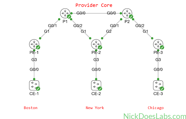
We will start with a fully functioning service provider core with 3 CSR1000v PE routers and 2 IOS XRd P routers. I’m using CSR1000v for the PE routers due to an issue with the IOS XRd data plane on VPLS. I’ve kept this topology small since CSR1000v is resource heavy compared to the containerized IOS XRd.
If you’d like to import the starting topology into Cisco Modeling Labs to follow along, you can download it here: CSR1000v Provider Core. If you are building this yourself make sure that you enable node staging and stagger the node priority to avoid overwhelming your Cisco Modeling Labs host.
- Customer Edge Switches (IOSvL2)
- CE-1
- CE-2
- CE-3
- Provider Edge Routers (CSR1000v)
- PE-1
- PE-2
- PE-3
- Provider Core Routers (XRd)
- P1
- P2
Step 1 – Adding the Customer Edge Switches
We’ll start by adding three customer edge switches to the topology. Each switch will get an IP address on its management interface and will connect to the PE router on Gi0/0. Configuring switches is outside the scope of this lab so I won’t walk you through it. However, the settings for the switches are summarized in this table:
| Hostname | IP Address | Connected To |
|---|---|---|
| CE-1 | 192.168.100.1/24 | PE-1 Gi3 |
| CE-2 | 192.168.100.2/24 | PE-2 Gi3 |
| CE-3 | 192.168.100.3/24 | PE-3 Gi3 |
This gives us the following topology:
Now we can begin configuring VPLS on the PE routers.
Step 2 – Configuring VPLS on the PE Routers
On each PE router we will first configure the customer-facing interfaces with no ip address. This tells the router that we are working with layer 2 only on these ports.
Next we will add the customer-facing interfaces to a service instance and a bridge domain. The service instance is a way of separating VPLS services on the same router. Each customer will get a different service instance. If a customer gets multiple services from the same PE router they may have multiple service instances to themselves. The bridge domain is the virtual “switch” that will learn customer MAC addresses and forward frames. Our customer will get service instance 100 and bridge domain 100.
We also need to specify the encapsulation type for the service instance before we configure the bridge domain. We aren’t using VLANs in this basic example so I’ve set the encapsulation type to untagged. This means that our bridge domain will accept any and all untagged frames. To make sure our frames are untagged, our switch ports on the CE devices will be configured as access ports.
The configuration hierarchy on the interface looks like this:
- Interface [interface number]
- no IP address
- service instance [number]
- encapsulation [type]
- bridge domain [number]
We then need to configure a Virtual Forwarding Interface (VFI) on the router. A VFI can be thought of as a layer 2 VRF. The VFI is where we will create our pseudowires via the neighbor command. We will also attach the VFI to the same bridge domain as the customer-facing interfaces (Gi3). Also we will give the VFI a VPN ID which will be used for forming the pseudowire neighborships with the other PE routers. I’ll use 100 as the VPN IDs well as the VFI name.
The configuration hierarchy for the VFI looks like this:
- l2 vfi [name] manual
- vpn id [number]
- neighbor [ip address] encapsulation mpls
- bridge-domain [bd number]
Here is a configuration example on PE-2:
interface Gi3
  service instance 100 ethernet
  encapsulation untagged
  bridge-domain 100
  exit
!
l2 vfi 100 manual
  vpn id 100
  bridge-domain 100
  neighbor 3.3.3.3 encapsulation mpls
  neighbor 5.5.5.5 encapsulation mpls
  end
The only difference in the configurations on PE-1 and PE-3 are the neighbor IP addresses.
Step 3 – Verifying the VPLS Configuration
We can begin verifying the VPLS configuration by running show bridge-domain 100 on each PE router.
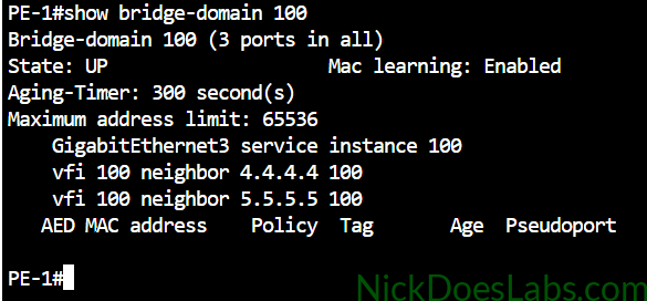
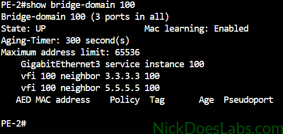
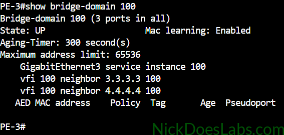
As you can see all of our bridge domains are up and contain 3 ports. The first port is the physical port going to the local CE switch. The other two ports are the pseudowires configured under the VFI.
Next, we can check the status of the vfi by running show l2vpn service vfi name 100.
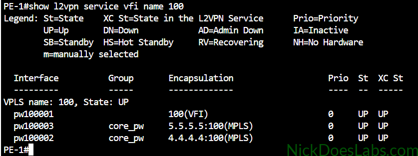
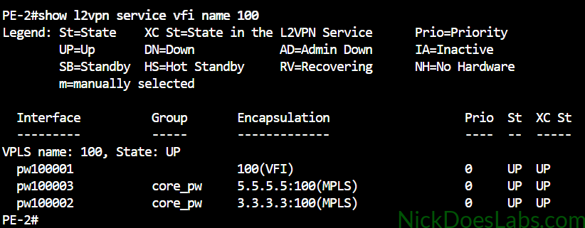
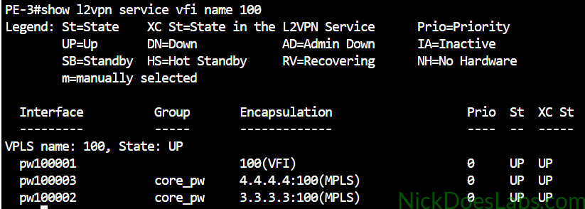
Here we can see the status of our local VFI group as well as the pseudowires to the remote VFIs.
I don’t want to inundate this post with screenshots so here is a table of other useful IOS XE show commands that you can run on the PE router to verify VPLS.
Step 4 – Sending Traffic Through VPLS Between CE Switches
| Command | What it Does |
|---|---|
| show xconnect all | Shows the state of all pseudowires |
| show mpls l2transport vc | Shows the state of pseudowires from an mpls point of view |
| show mpls l2transport vc detail | Additional information for troubleshooting why a pseudowire is down |
| show ethernet service instance | Shows the state of the local customer-facing interface (Attachment Circuit) |
| show ethernet service instance detail | Additional information for troubleshooting why a service instance is down. |
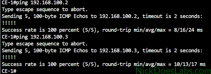
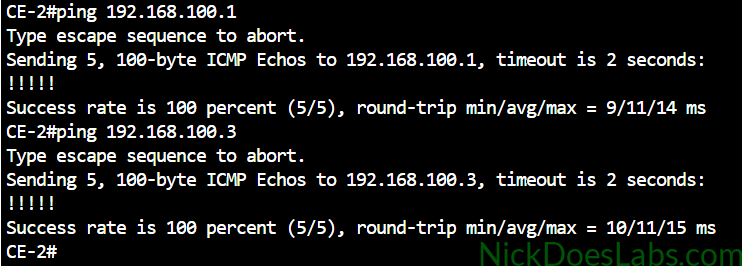
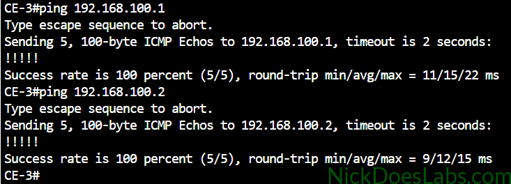
Next, we will ping each CE switch’s vlan1 IP address from each other CE switch.
I’ll also confirm that CE-1 has learned the MAC addresses of the other CE switches’ VLAN 1 and Gi0/0 interfaces.
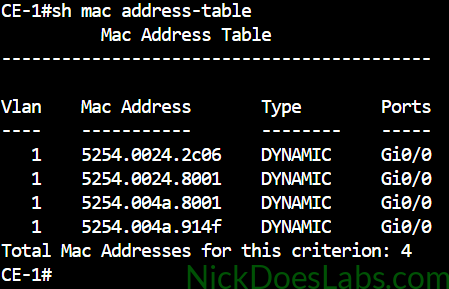
This demonstrates that we have a true layer 2 VPN. Also note that the service provider’s network is transparent to the customer. The CE switch has not learned any MAC addresses from the PE routers, only the other two CE switches.
Step 5 – Verifying MAC Learning on the PE Routers
Although the CE switches don’t learn any MAC addresses from the provider’s equipment, the opposite does happen. The bridge domain on the PE routers does learn the MAC addresses of the customer devices. This allows the PE routers to only send frames where they need to go once MACs are learned. This reduces MAC flooding. If you want to learn more about how VPLS works, see my article: How VPWS and VPLS Layer 2 VPNs Work.
To verify that the PE routers are learning MAC addresses we can run the command show bridge-domain 100.
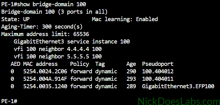
Here we can see that PE-1 has learned the MAC addresses of the three switches’ Gi0/0 ports. It hasn’t learned the SVI MAC addresses yet because I ran the pings from the physical interfaces. However if I go back and run the pings with a source of Vlan1 on each switch, the PE router will learn Vlan1’s MACs.
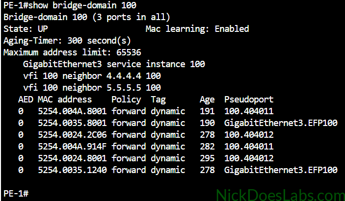
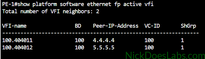
Note that we can tell which MAC addresses were learned through the local GigabitEthernet 3 port and which were learned remotely via pseudowires. The pseudoport to pseudowire mapping on IOS XE can be retrieved with show platform software ethernet fp active vfi. This tells us which neighbor each pseudoport belongs to.
Conclusion
We have successfully built a VPLS layer 2 VPN in Cisco Modeling Labs. We used IOS XE on the CSR1000v image to implement the VPLS service for our customer. Then, we verified layer 2 reachability between the customer’s CE switches in three different cities. Finally, we confirmed that our PE routers were properly learning MAC addresses from the customer switches.
You can download the lab.yaml file to import into CML as well as the configuration files for each node for free here: L2VPN_VPLS_configs. For more detailed information on VPLS configuration see the Cisco Docs: How to Configure Virtual Private LAN Services.