Introduction
The concept of a leased line, where a customer pays a service provider for a private WAN connection predates computer networking. In fact, the origins of the leased line were in the telegraph days. Over the years the term has been used to describe a multitude of different services. It’s easy to confuse different service types and separate legacy vs modern services.
As I’ve studied networking, I’ve found that a lot of courses abstract away from what a leased line actually is. There’s a reason for this, it can get really complicated and much of the details don’t affect the customer. For someone who is interested in carrier networking it can be frustrating when diagrams just show WANs as serial links. Why serial? How does the carrier make a private serial connection stretch between cities? I’ve decided to give a history lesson on leased lines case anyone else is curious about these things.
Pre T-Carrier Leased Copper (Pre 1962)
Before routers and computers, the majority of business communication was done either by phone, in person, or snail mail.
Companies would have a switchboard operator to connect calls to either the Public Switched Telephone Network (PSTN) or internal extensions. Internal calls within an office would just ride over copper in the same building. But what if a company had multiple offices? In this case they would request a leased line.
Early leased lines were often dedicated metallic circuits that were physically cross-connected through telco central offices. As demand grew and distances increased, carriers began using analog multiplexers to put multiple voice circuits on shared transmission wires. The first of these multiplexing technologies was frequency division multiplexing (FDM). FDM took multiple voice circuits and placed each one on a different frequency. That combined signal then traveled on a single copper pair. At the far end, frequency filters would split the signal back into its channels.
Technicians would place copper jumpers along the path, cross-connecting the circuit between various transmission cables to get to its destination. Things like load coils and vacuum tube repeaters in the providers network kept the signal viable over long distances. However the provider didn’t actually connect calls to the line, that was up to the customer’s switchboard operators.
The Digital Age, T-Carrier and PBXs (1960s – 1970s)
By the 1960s and 1970s the T-Carrier system and the Private Branch Exchange (PBX) became popular. The PBX replaced company switchboards operators with an automated system. PBXs could route calls to internal extensions or the PSTN. They could also peer with remote PBXs to allow internal extension calls between offices.
A T1 is a digital Pulse Control Modulation (PCM) signal which carries 24 digital voice channels on two copper pairs. The T1 works by sampling each voice channel 8000 times per second. Each sample is 8 bits of data which represents the amplitude of the analog waveform at that moment in time. The T1 transmits this sequentially in pulses that are terminated by a framing bit:
- 8 bits from channel 1
- 8 bits from channel 2
- …
- 8 bits from channel 24
- Frame (1 bit)
Frames are transmitted at 8,000 times per second and contain 193 bits per frame. Therefore the T1 has a bandwidth of 193 bits x 8,000 cycles/second = 1.544 Mbps.
Single channels on a T1 are called DS0s (Digital Signal 0). DS0s are at the bottom of the T-Carrier hierarchy. A DS0 has a bandwidth of 8 bits x 8,000 cycles/second = 64,000 bits/second or 64 Kbps.
T1s quickly became the way to connect PBXs to each other and to the PSTN. They also became heavily used within carriers to transport customer calls between central offices and equipment.
What Does this Have to Do With Networking?
I’m getting there. As T-Carrier was taking over the telephone world, the internet was in its infancy. Engineers realized that computer data could also be transmitted over DS0 lines since it is a digital signal. In a voice DS0 the analog voice signal is what is sampled and reconstructed on the far end. Therefore to send data, engineers converted it to an analog signal which could travel through the existing telephone network. This process is called Modulation and Demodulation and is done by a device known as a Modem.
Consumer dial-up modems allowed home users to access Internet Service Providers over ordinary telephone lines. Although a DS0 provides 64 Kbps, limitations in the telephone network meant that dial-up modems maxed out at 56 Kbps. ISPs like AOL built countless racks of modems to accept incoming calls and connect customers to the internet.
DS0 and DS1 Leased Lines (1980s – 1990s)
As businesses embraced modern networking, carriers allowed them to lease private DS0s or DS1s to run between their offices. A DS1 is another word for T1, usually used when data is being sent. To transmit the data, providers gave customers Channel Service Units/Data Service Units (CSU/DSU). The CSU/DSU would terminate the T1 and provide a serial interface for the customer to connect their router.
The leased T1 line was the most popular method of interconnecting remote offices during this time. This is why Cisco serial links default to a bandwidth of 1.544 Mbps (T1). This is also why traditional enterprise network documentation depicts WAN links as serial point-to-point connections.
A leased T1 appeared to the customer as a direct layer 1 connection. Behind the scenes, carriers moved T1s over long distances using T3s, DACS systems and SONET multiplexers. These systems maintained the privacy of the channels by giving each channel a time slot to transmit its data. Everything in a specific time slot belonged to a specific circuit and would only be forwarded along that circuit’s path. This is known as Time Division Multiplexing (TDM).
Fiber Optics and SONET (1990s – 2000s)
In the mid to late 1980s fiber optics became commonplace in carrier networks. The SONET protocol was born, which could take DS0s, DS1s, and DS3s and encapsulate them further into higher bandwidth links. SONET standardized rates up to OC-768 (39.813 Gbps).
As carriers deployed fiber in the field, customers were no longer limited to copper. They could now purchase high-speed SONET services delivered over fiber. These were still private lines which the service provider transported through SONET rings. SONET rings were a group of TDM multiplexers connected in a ring topology throughout a region. They could add or drop circuits as needed, leading them to also be known as Add/Drop Multiplexers (ADM).
DS0, DS1, DS3, and SONET are generally considered Physical Layer (Layer 1) transport technologies. However, they do include framing and management functions that don’t fit perfectly into the OSI model. Even though there may be a long and complex transport path for a circuit customers see a private direct connection.
This is a good time to mention Dark Fiber. Most of the time when engineers talk about leased lines we do not mean dedicated fiber strands. Leased lines are generally private circuits running through a SONET, OTN, or MPLS network. In some cases, it is possible to lease physical fiber strands from an ISP. In those cases, the ISP makes the splices and connections to give the customer a dedicated fiber path. The customer puts their own service on the fiber. This is common when one provider needs fiber in an area where they don’t have any, but another provider does.
Frame Relay and Asynchronous Transfer Mode (ATM) (1990s)
I know less about these two technologies than T1s and T3s because they just didn’t survive very long. Frame Relay and ATM were layer 2 WAN technologies that provided lower cost alternatives to private circuits like leased T1s.
With frame relay instead of customers getting their own private T1s, providers connected them to a shared switching infrastructure. Data was switched with frames that were similar to but not the same as Ethernet frames. Customers would be given virtual circuits through the network that were identified by DLCIs. Frame relay switches cross-connected these virtual circuits to give customers the appearance of a dedicated circuit without the cost. The downside was that frame relay switches were literally just switches. They did not perform routing and offered only limited traffic management capabilities compared to later technologies.
ATM was an attempt to build a network protocol that would carry voice, data and video simultaneously (before VoIP). To minimize delay for voice and video, ATM broke data into 53 byte cells to allow extremely fast switching. ATM also used virtual circuits to connect customer sites privately, and it also supported QoS. Because it was optimized to carry voice and data together, ATM became heavily used in DSL aggregation. ATM was complicated and wasted bandwidth since packet was broken into 53 byte cells (each with a 5 byte header). Because of this VoIP quickly overtook ATM as the preferred method of switching voice traffic in modern networks.
Modern Leased Lines – MPLS EVCs and VPNs
MPLS was invented in the mid to late 1990s as an alternative to frame relay and ATM. The goal was initially to combine the speed of ATM with the flexibility of IP. MPLS encapsulates IP packets with labels, allowing routers to rapidly forward traffic without performing a route lookup for each packet.
As ASICS improved routing speed, this became less important, however MPLS still has big advantages. MPLS supports powerful QoS and Traffic Engineering capabilities via RSVP-TE and Segment Routing. Labels can be distributed using protocols such as LDP, RSVP-TE, Segment Routing, or BGP Labeled Unicast (BGP-LU). This gives providers flexibility in core network design. MPLS also supports encapsulating data with VPN labels for L3VPNs, pseudowire labels for L2VPNS. Pseudowires are the modern MPLS equivalent to ATM and Frame Relay virtual circuits. These days ethernet is used for the handoff to the customer router instead of serial.
L2VPNs are defined in IEEE carrier ethernet standards as Ethernet Virtual Connections (EVCs). E-Line is the standardized name for point-to-point Layer 2 VPNs. E-LAN is the standardized name for multipoint Layer 2 VPNs. EVCs are generally implemented using MPLS pseudowires. In technical terms they’re called VPWS for point to point and VPLS for point to multipoint. MPLS EVCs are now the dominant type of WAN connection between customer offices, alongside L3VPNs and EVPNs. MPLS pseudowires allow providers to implement EVCs using their MPLS core, rather than aging SONET rings.
Modern Carrier Transport – OTN
Sonet is slowly being replaced with a new protocol, Optical Transport Networking (OTN). OTN functions similarly to SONET except it runs alongside Dense Wavelength Division Multiplexers (DWDM). Thanks to DWDM, OTN supports much higher bandwidth than SONET. The base unit of OTN is the ODU0 (1.25 gbps) and the highest standardized unit is the ODU4 (100 gbps). Bandwidths higher than 100gbps are also possible through custom ODU sizes on modern equipment.
OTN serves an important role in provider backbones by transporting customer circuits from customer locations to the PE routers. It also provides transport circuits for backbone connections between PE routers, core routers, and OLTs. If a customer needs a high bandwidth point-to-point layer 1 link, they can lease OTN wavelengths directly from carriers. This is commonly known as Wavelength Services or Optical VPN. A leased OTN wavelength is analogous to the old school leased T1 line, but with much higher bandwidth and distance capability.
For more information on DWDM and OTN, see the Ciena Documentation: What is Optical Transport Networking and What is WDM or DWDM.
Conclusion
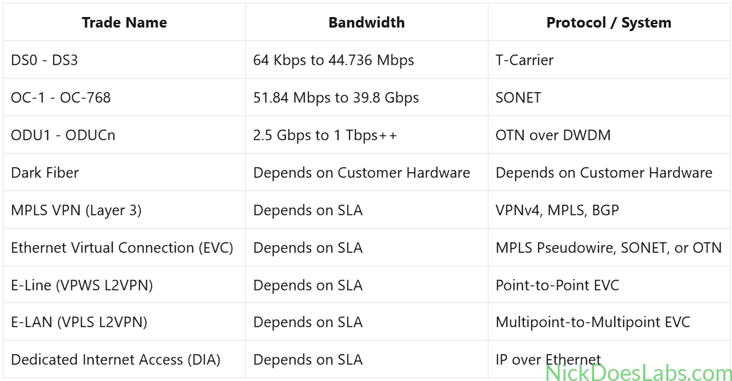
We have traced the history of the leased line, beginning with dedicated copper pairs and ending with OTN wavelengths. The term leased line can be used to refer to several distinct technologies, including:
| Trade Name | Bandwidth | Protocol / System |
|---|---|---|
| DS0 – DS3 | 64 Kbps to 44.736 Mbps | T-Carrier |
| OC-1 – OC-768 | 51.84 Mbps to 39.8 Gbps | SONET |
| ODU1 – ODUCn | 2.5 Gbps to 1 Tbps++ | OTN over DWDM |
| Dark Fiber | Depends on Customer Hardware | Depends on Customer Hardware |
| MPLS VPN (Layer 3) | Depends on SLA | VPNv4, MPLS, BGP |
| Ethernet Virtual Connection (EVC) | Depends on SLA | MPLS Pseudowire, SONET, or OTN |
| E-Line (VPWS L2VPN) | Depends on SLA | Point-to-Point EVC |
| E-LAN (VPLS L2VPN) | Depends on SLA | Multipoint-to-Multipoint EVC |
| Dedicated Internet Access (DIA) | Depends on SLA | IP over Ethernet |
I hope that this article is helpful in understanding the history of leased lines and different types of services that providers offer for WAN connectivity.