Overview
VyOS is an open source virtual network operating system which is fully customizable, with all of the source code readily available on github. It allows users to spin up virtual routers at no cost in the cloud, on VMs, or on bare metal. VyOS has several use cases with the capability to act as a Cloud Gateway, VPN Gateway, Broadband Network Gateway, enterprise edge router or ISP border router. For more information on VyOS, see https://vyos.io/vyos-platform.
Step 1 – Downloading the VyOS Image
The semi-stable VyOS image is available for free as an .iso file from the VyOS stream downloads page: https://vyos.net/get/stream/. Stable LTS versions are available to contributors, non-profits, and paid subscribers. For more information see https://vyos.net/get/. I don’t recommend using a rolling release unless you are interested in testing VyOS but those are available as well.
There isn’t a .qcow2 image available so we will need to convert the file from .iso to qcow2. We’ll do this next.
Step 2 – Converting from .iso to .qcow2
An .iso image is generally a file containing an operating system’s installer. A .qcow2 image is a virtual disk file containing whatever operating system is installed on it. So in order to convert the VyOS .iso to a .qcow2 image we first need to install it into a virtual machine’s disk.
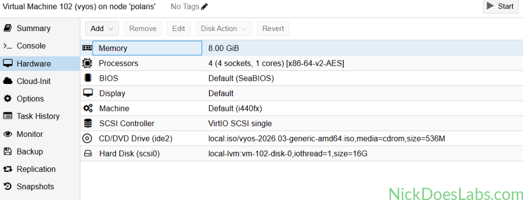
Since I use Proxmox for my homelab, I’ll be using it to accomplish this. However, you can use any linux based system running qemu. Do NOT give the vm a network interface, it will trick vyos into thinking there should be an extra interface which CML will not be able to emulate. Trust me, I learned this the hard way. Also, since this is technically a qemu VM, you can install the qemu virtual agent. My settings on Proxmox look like this.
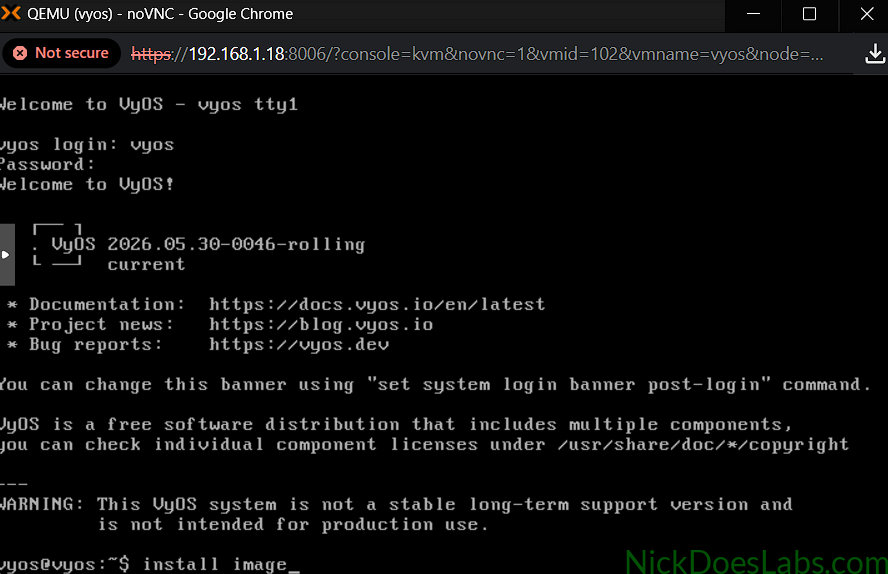
Once you boot the VM, log in with the username and password vyos,vyos. Then, run the command “install image” to install VyOS on the virtual disk.
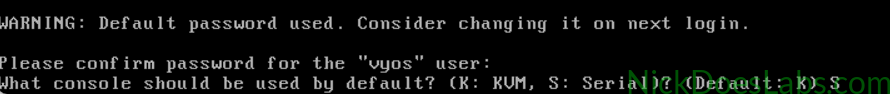
I left all the settings default except for the default console, i set that to Serial since CML will emulate a serial connection. I kept the default username and password of vyos,vyos.
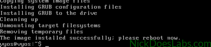
Once you see that the installation is complete, reboot the vm. Once it comes back up, you can shutdown the vm and find the location of the virtual disk. On Proxmox I’ll do this using qm config [vm id].
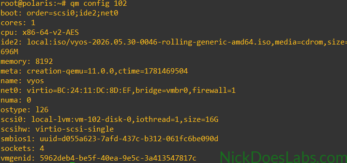
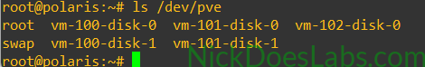
You can see that my virtual disk for this VM (scsi0) is stored in local-lvm as vm-102-disk-0. On Proxmox local-lvm is located at /dev/pve by default. I can use ls to verify that i see the disk.
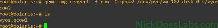
To convert the disk to a .qcow2 format I’ll run the command qemu-img convert -f raw -O qcow2 /dev/pve/vm-102-disk-0 ~/vyos.qcow2. Once that completes, I’ll use ls again to verify that I see the .qcow2 file.
At this point I used scp to copy the .qcow2 file to my computer where I then uploaded it to Cisco Modeling Labs.
Step 3 – Uploading the Image to CML
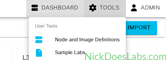
In Cisco Modeling Labs navigate to Tools > Node and Image Definitions. Then, navigate to Image Definitions > Manage.
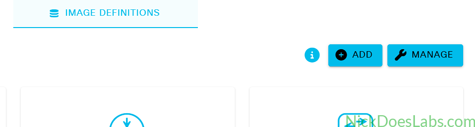
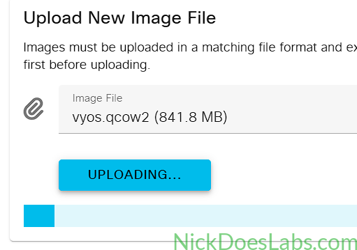
This will bring you to the Image File Upload screen where you can upload your .qcow image.
Step 4 – Creating the Node Definition
If you want to skip this step, you can download the node definition .yaml file that I created here.
If you want to follow along, first go back to Tools > Node and Image Definitions. Then under Node Definitions, click Add. This will open up the node definition screen. Configure it as follows.
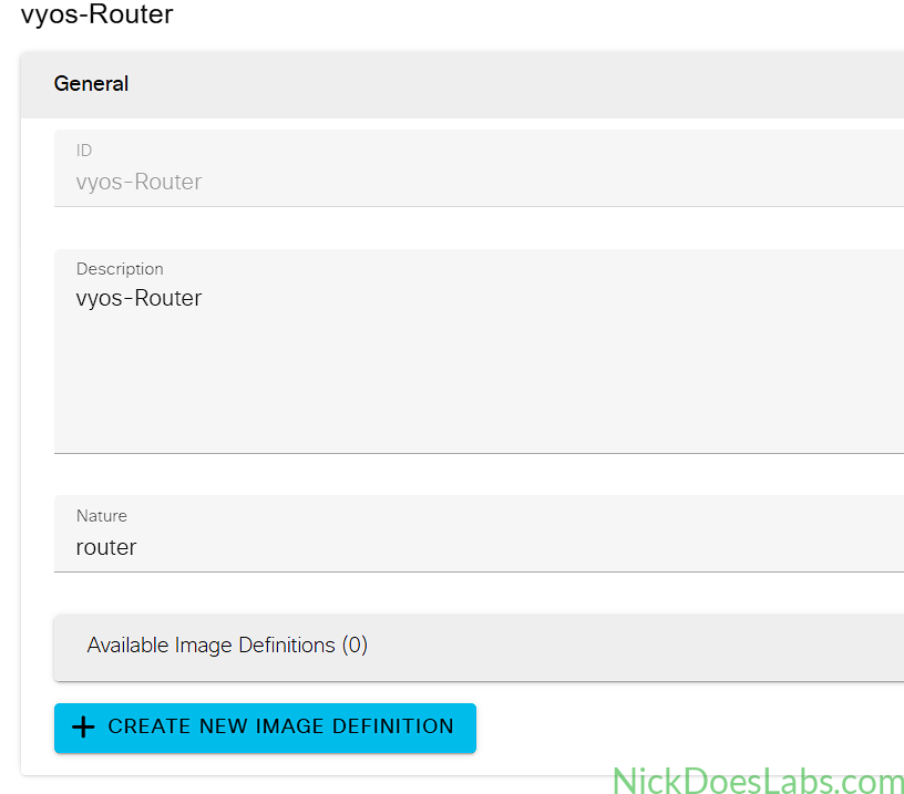
For the General section I gave the node an id of vyos-Router and a description of vyos-router. Set the nature to router and leave the image definition blank.
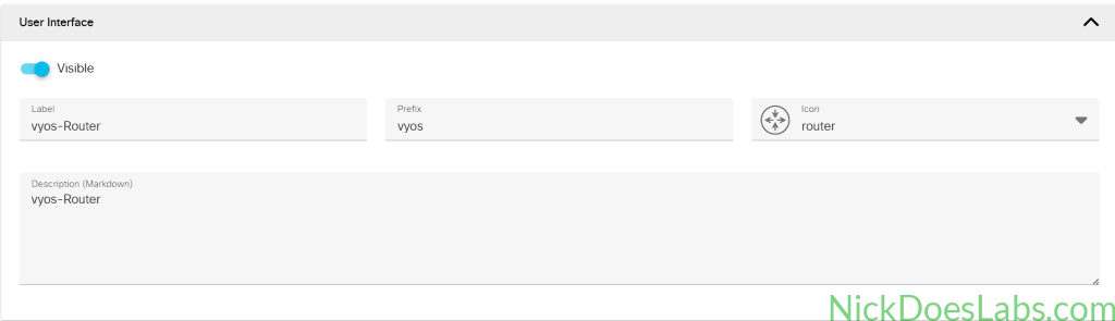
For the User Interface Section I gave the node a Label of vyos-Router and a Prefix of vyos and had it use the Router Icon.
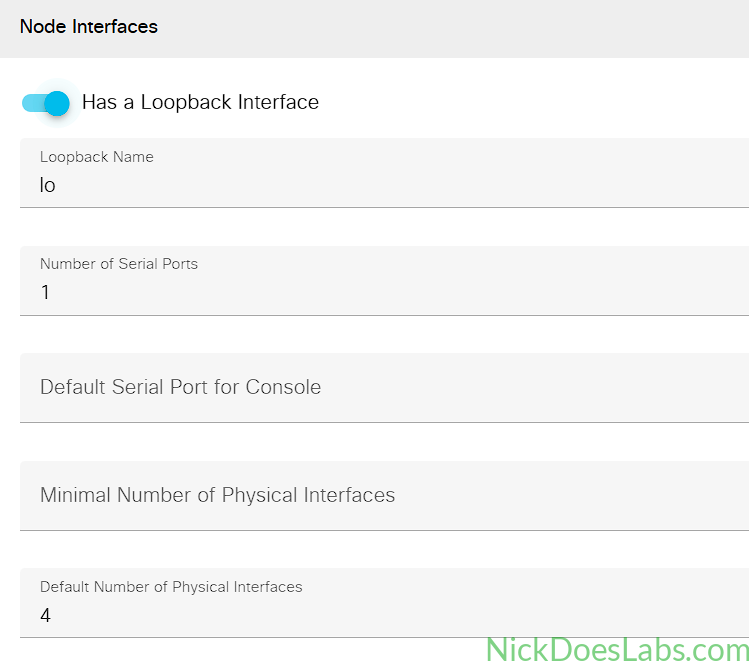
For node interfaces, VyOS does have a default Loopback interface named “lo” so we will specify that here. Also give the node 1 serial port and 4 default physical Interfaces.
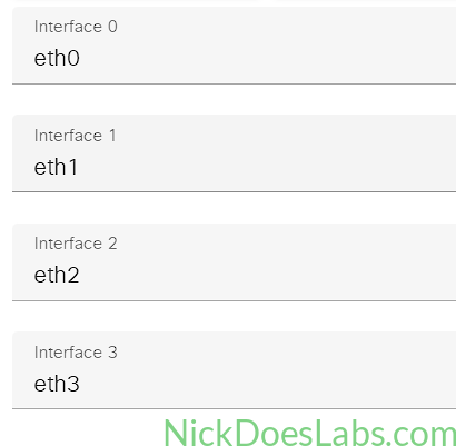
Next we will specify the interfaces as eth0, eth1, eth2, and eth3.
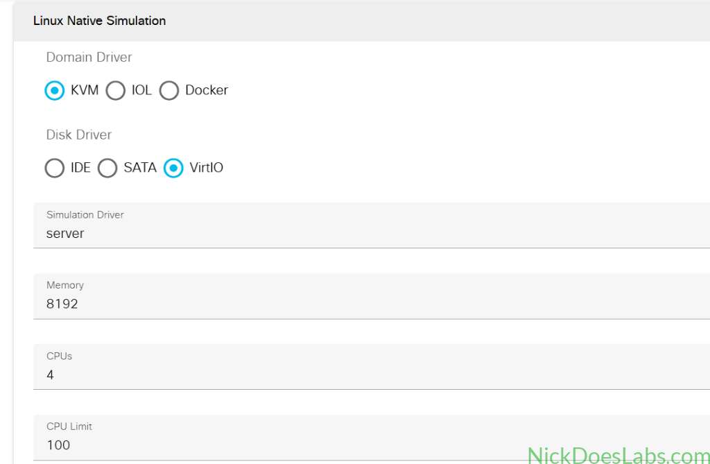
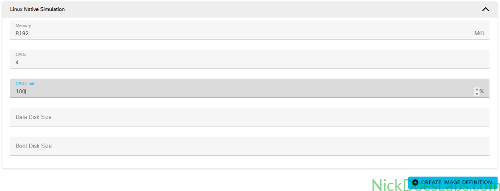
Finally under Linux Native Simulation we will set the domain driver to kvm, the disk driver to VirtIO, and the network driver to VirtIO. We will also give the node 8gb of memory and 4 vCPUs with a CPU limit of 100%.
Step 5 – Creating the Image Definition
If you want to skip this step, you can download the image definition .yaml file that I created here.
Once you’ve saved your node definition, go back to the top where you’ll find the “Create Image Definition” button and click on it. This opens the Image Definition Editor where will will configure the following General information.
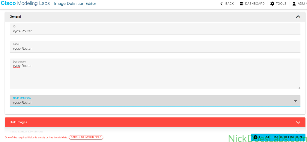
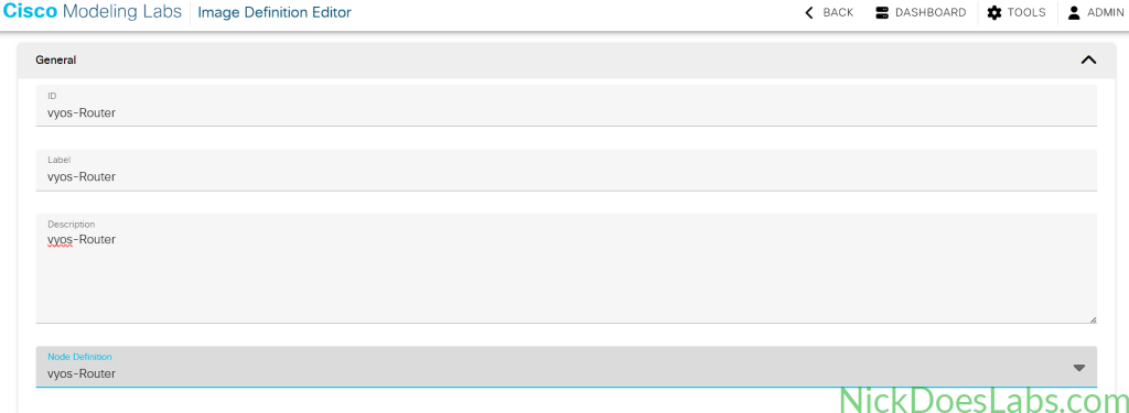
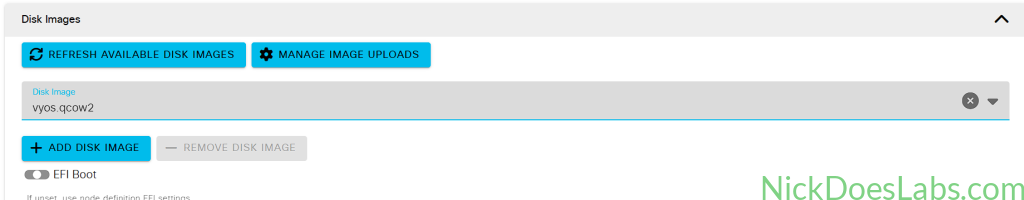
Then, under Disk Images, select the vyos.qcow image that you uploaded earlier.
Finally, under Linux Native Simulation we will configure the same resources as we did earlier in the Node Definition.
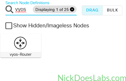
You can then save your image definition and open any lab. You will now see vyos-Router as an available node.
Step 6 – Verifying the VyOS-Router Node
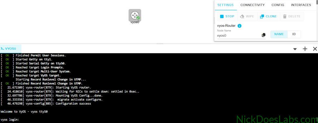
We can now add the node to our lab and start it up to verify it is working properly. Once it boots you’ll see a login screen where you can log in with the username and password “vyos” (unless you changed it earlier).
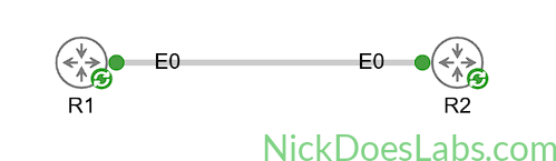
Finally, I’m going to add two Vyos Router nodes to my topology, connect them, and verify that they can ping each other.
!!! R1 !!!
config
set interfaces ethernet eth0 address 10.0.0.1/30
commit
save
!!! R2 !!!
config
set interfaces ethernet eth0 address 10.0.0.2/30
commit
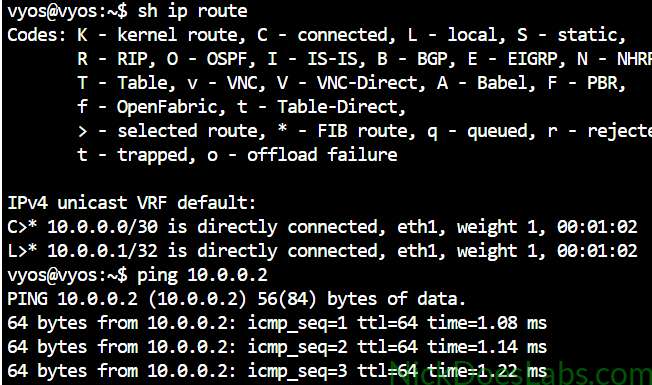
saveAfter making the connection and assigning IP’s based on the mac addresses, we can ping between the nodes.
Conclusion
We were able to import VyOS Router into Cisco modeling labs by first converting the .iso file into a .qcow2 disk image and then creating node and image definitions in Cisco Modeling Labs.