Overview
In this lab we will construct a layer 2 point-to-point Virtual Private Wire Service (VPWS) in Cisco Modeling Labs. We will use IOS XRd images for our Provider Edge and Core routers and IOSv images for the customer routers.
Scenario
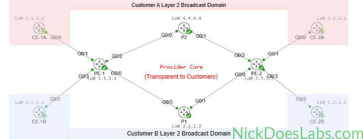
Customer A and Customer B both have 2 sites in different cities. Both customers have requested private layer 2 connections between their respective offices from their service provider. Neither customer will be able to see each other’s traffic, despite connecting to the same equipment at the service provider.
Method
There are many ways to provide a customer with a private layer 2 circuit. This lab focuses on the technology known as Virtual Private Wire Service (VPWS). VPWS allows the provider to use their MPLS core as a layer 2 transport path for the customer’s traffic via pseudowires. This technology was one of the key drivers behind providers migrating from SONET/TDM-based leased-line services toward packet-based MPLS transport networks. For more info on VPWS, Juniper has a great explanation here.
Equipment
I’ll be using the same equipment that I used in my Layer 3 MPLS VPN lab. If you’d like you can download the base template here to follow along, you’ll just need to make some adjustments to the customer routers. I’m starting with a fully configured provider MPLS core with IS-IS as the IGP. If you’d like instructions on configuring IS-IS and MPLS see Building a Service Provider MPLS Core in Cisco Modeling Labs.
- Customer Edge Routers (IOSv)
- CE-1A
- CE-1B
- CE-2A
- CE-2B
- Provider Edge Routers (XRd)
- PE-1
- PE-2
- Provider Core Routers (XRd)
- P1
- P2
Step 1 – Configuring the Provider Edge Routers
VPWS uses the term cross-connect to describe how pseudo-wires are connected in the router’s configuration. I love this as it is a legacy term carried over from the old SONET/TDM Multiplexing days where a DACS would manage cross connects between T1s and T3s. Anyway, to configure our pseudowires we will need to configure a xconnect group for each Customer on the ingress and egress PE routers. This xconnect group will contain groups of cross connects belonging to a specific customer.
Within the cross connect group we will specify each cross connect with its topology type and a unique cross connect name. The topology type will tell the router the type of l2vpn we are implementing, point-to-point (VPWS) or multipoint (VPLS). In this case we are implementing point-to-point but when we cover VPLS we will use multipoint. Within the cross-connect configuration we will specify which interfaces belong to that cross connect and what neighboring PE router the pseudowire should connect to.
When we specify the cross connect neighbor we must also specify a pseudowire id (pw-id) which must match on the neighboring router to allow the cross connect to be established. The pw-id is used to identify the specific pseudowire between the PE routers and ensure that the correct attachment circuits are connected together.
Just to recap before I paste the configs, the configuration hierarchy for each L2VPN on the PE router is:
- xconnect group
- xconnect topology and name
- interface
- neighbor (and pw-id)
- xconnect topology and name
Here are the complete configurations:
!!! On PE-1 !!!
config
l2vpn
  xconnect group CUSTOMER_A
    p2p vpws_A
      interface gi0/0/0/1
      neighbor 3.3.3.3 pw-id 100
      exit
    exit
  xconnect group CUSTOMER_B
    p2p vpws_B
      interface gi0/0/0/3
      neighbor 3.3.3.3 pw-id 200
      exit
    exit
   interface gi0/0/0/1
     l2transport
     no shutdown
   interface gi0/0/0/3
     l2transport
     no shutdown
   commit
end
!!! On PE-2 !!!
config
l2vpn
xconnect group CUSTOMER_A
p2p vpws_A
interface gi0/0/0/1
neighbor 1.1.1.1 pw-id 100
exit
exit
xconnect group CUSTOMER_B
p2p vpws_B
interface gi0/0/0/3
neighbor 1.1.1.1 pw-id 200
exit
exit
interface gi0/0/0/1
l2transport
no shutdown
interface gi0/0/0/3
l2transport
no shutdown
commit
endStep 2 – Verify the Pseudowires
On each PE router we can verify the pseudowires using the show l2vpn xconnect command. This will give us the following output.
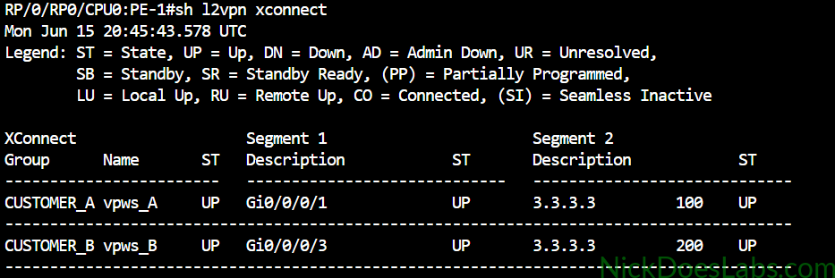
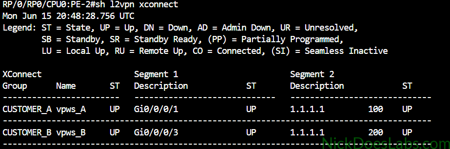
As you can see each router shows the cross-connect state UP as well as a local and remote state of UP.
Step 3 – Verifying Connectivity on the CE Routers
I’ve configured ospf on the CE Routers. I won’t go into detail on that configuration here since it is outside the scope of this article. All networks are in area 0 and I manually assigned OSPF router IDs to make the neighborships easier to identify in the output. Here’s a brief overview for reference:
| Router | Loopback | OSPF Router ID | Networks | Gi0/0 IP Address |
|---|---|---|---|---|
| CE-1A | 1.1.1.1 | 10.0.0.0 | 10.0.0.0/30 1.1.1.1/32 | 10.0.0.1 255.255.255.252 |
| CE-2A | 2.2.2.2 | 12.12.12.12 | 10.0.0.0/30 2.2.2.2/32 | 10.0.0.2 255.255.255.252 |
| CE-1B | 1.1.1.1 | 11.11.11.11 | 10.0.0.4/30 1.1.1.1/32 | 10.0.0.5 255.255.255.252 |
| CE-2B | 2.2.2.2 | 13.13.13.13 | 10.0.0.4/30 2.2.2.2/32 | 10.0.0.6 255.255.255.252 |
On each router I will confirm the OSPF neighborship is up and I can ping the neighboring router.
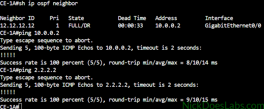
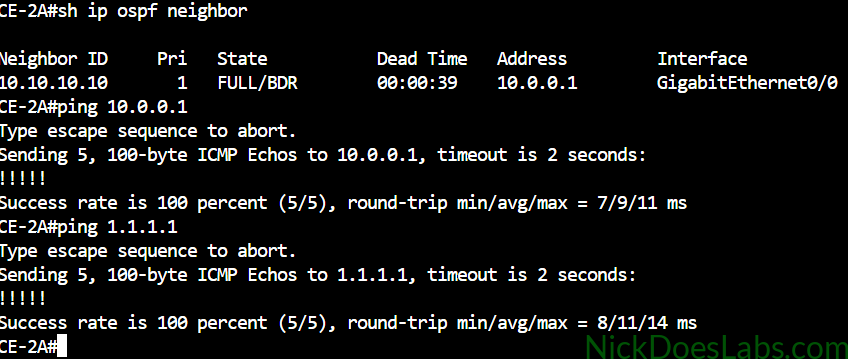
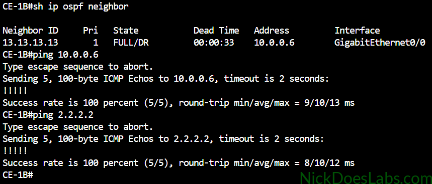
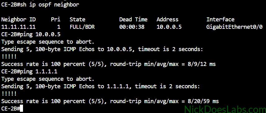
As you can see the neighborships were formed directly with the router on the other end of the VPWS pseudowire. The customers do not see the provider edge routers at all, the entire provider network is transparent to the customer.
Bonus – Testing With Layer 2 Switches
To further demonstrate that we are extending layer 2, I will perform a test with layer 2 switches in place of the CE routers. This would be an unusual topology in the real world. While there are cases where you want the same Layer 2 broadcast domain in two locations, technologies such as EVPN/VXLAN generally provide a more scalable solution when extending Layer 2 across many sites. Typically a VPWS customer is running some sort of routing protocol on top of the L2VPN like I just demonstrated. Regardless, for science lets take a look.
I’m going to replace Customer A’s routers with layer 2 switches. I’ll configure a management SVI on each switch that will match the IP addresses we used on the respective routers.
| Switch | Int VLAN 1 IP Address | Int Gi0/0 MAC |
|---|---|---|
| Switch_A1 | 10.0.0.1 255.255.255.252 | 5254.001d.2766 |
| Switch_A2 | 10.0.0.2 255.255.255.252 | 5254.009c.d17e |
Then I’ll connect each switch’s Gi0/0 port to the PE router. This gives us the following topology:
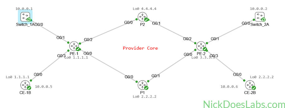
To verify layer 2 connectivity between the switches I’ll run the commands show cdp neighbors, show mac address-table, and I’ll ping between the 2 management SVIs.
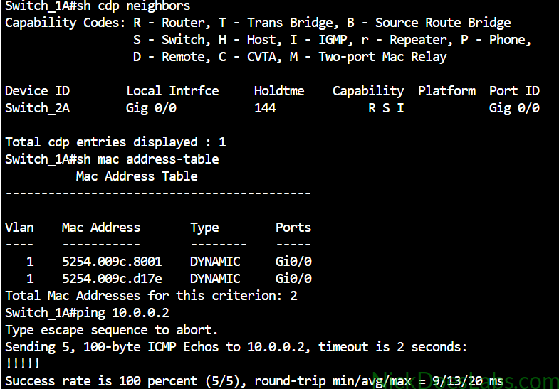
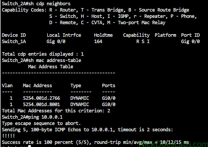
The MACs ending with .8001 are the neighboring switch’s Vlan1 interface. And the other MAC is the neighboring switch’s interface gi0/0. As you can see we see no indication of the provider’s network at all. These switches think that they are directly connected to each other. This is the magic of the layer 2 VPN.
Conclusion
We have learned how to configure a VPWS Layer 2 VPN, how to configure pseudowires on IOS XR, and how a layer 2 point-to-point VPN works. We built a topology in Cisco Modeling Labs where a service provider successfully transported 2 customer’s layer 2 traffic over their MPLS core. The pseudowires kept the traffic separate and the entire provider network was transparent to the customer’s equipment. You can download the completed configuration files and Cisco Modeling Labs lab.yaml file here.