
Overview
Multicast is a type of IP traffic which facilitates one-to-many communication. In this lab we will learn how to configure multicast routing. In multicast, client computers subscribe to a multicast group, which is identified by a multicast IP address. This subscription is initiated and terminated via IGMP messages. Once a client is subscribed to a group, routers use PIM to construct a path between that client and the server. This path is known as a PIM tree. The primary use cases of multicast are real-time one-to-many streaming applications such as IPTV, security cameras, or digital signage. Familiarity with multicast is a necessity for all Network Engineers.
Scenario
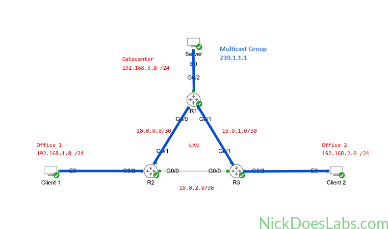
A company has two offices and a data center connected through a WAN. The data center houses a server that provides a real-time video feed for digital signage in the offices. We need to configure multicast so the server in the data center can transmit the video stream to the digital signage receivers at both offices.
Method
We will configure Protocol Independent Multicast (PIM) Sparse Mode on all routers in the enterprise. R1 will act as both the Bootstrap Router (BSR) and the Rendezvous Point (RP), using Loopback 0 as the address for both functions. R2 and R3 will learn the RP mapping through BSR. Because PIM is enabled on the office-facing interfaces, IGMP will also be enabled there so the routers can learn which local clients have joined multicast group 239.1.1.1.
Equipment
- Routers (IOSv Node)
- R1
- R2
- R3
- Servers (Desktop Node)
- Server
- Signage (Desktop Node)
- Client 1
- Client 2
Step 1 – Basic Configuration
I’ll start by adding all of the nodes and connecting them to create the following topology:
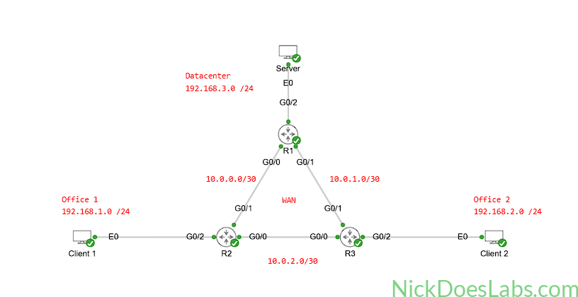
Next, I’ll make the following IP configurations on all routers:
| Router | G0/0 | G0/1 | G0/2 | Lo0 |
|---|---|---|---|---|
| R1 | 10.0.0.1 /30 | 10.0.1.1 /30 | 192.168.3.1 /24 | 1.1.1.1 /32 |
| R2 | 10.0.2.1 /30 | 10.0.0.2 /30 | 192.168.1.1 /24 | 2.2.2.2 /32 |
| R3 | 10.0.2.2 /30 | 10.0.1.2 /30 | 192.168.2.1 /24 | 3.3.3.3 /32 |
Then, I’ll configure static IP addresses on the end devices:
| End Device | IP Address |
|---|---|
| Client 1 | 192.168.1.2 |
| Client 2 | 192.168.2.2 |
| Server | 192.168.3.2 |
Finally, I’ll use the following commands to configure OSPF in the network.
!!! R1 !!!
conf t
router ospf 1
router-id 1.1.1.1
  area 1 stub
  passive-interface Lo0
  network 192.168.3.0 0.0.0.255 area 1
  network 1.1.1.1 0.0.0.0 area 0
  network 10.0.0.0 0.0.0.3 area 0
  network 10.0.1.0 0.0.0.3 area 0
end
wr mem
!!! R2 !!!
conf t
router ospf 1
router-id 2.2.2.2
area 1 stub
passive-interface Lo0
network 192.168.1.0 0.0.0.255 area 1
network 2.2.2.2 0.0.0.0 area 0
network 10.0.0.0 0.0.0.3 area 0
network 10.0.2.0 0.0.0.3 area 0
end
wr mem!!! R3 !!!
conf t
router ospf 1
router-id 3.3.3.3
area 1 stub
passive-interface Lo0
network 192.168.2.0 0.0.0.255 area 1
network 3.3.3.3 0.0.0.0 area 0
network 10.0.1.0 0.0.0.3 area 0
network 10.0.2.0 0.0.0.3 area 0
end
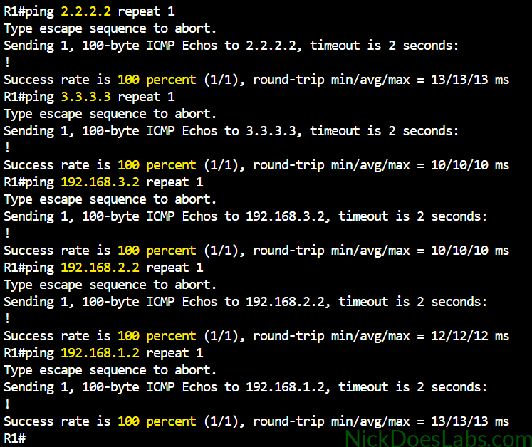
wr memBefore we move forward, let’s verify that routing is working properly and we have reachability throughout the network. First, I’ll run show ip route to verify that OSPF is working properly:
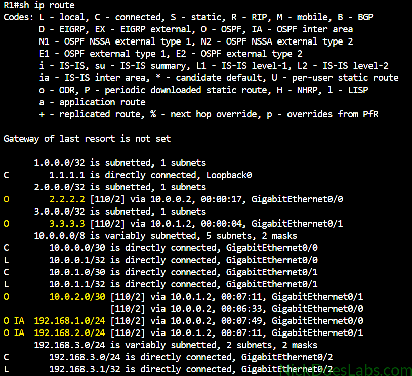
I see the remote LAN subnets, the WAN transit subnets, and the loopbacks of the other routers. Next, I’ll use ping commands on R1 to verify connectivity to the end devices as well as between the routers:
Finally, let’s confirm connectivity between the server and clients:
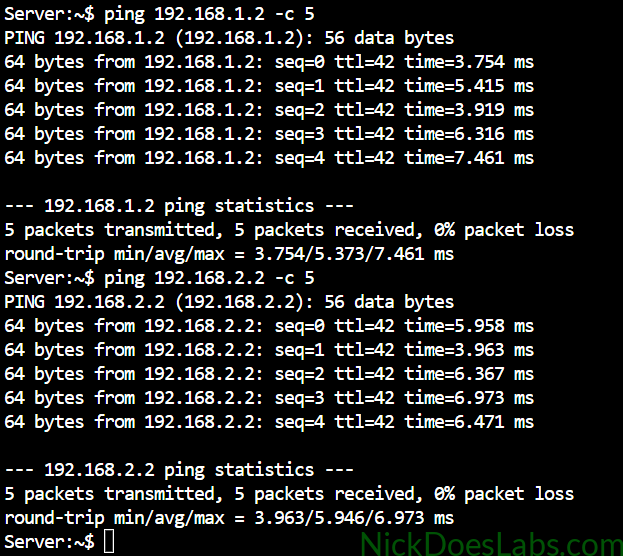
With end-to-end connectivity confirmed, we are ready to move on to multicast configuration.
Step 2 – Configuring the Multicast Clients and Server
Before we actually configure IGMP and PIM on our routers, let’s use iPerf to generate and receive multicast traffic on the server and clients. The reason I am using the default “Desktop” node for both the clients and the server is that it includes iPerf by default. This means that we don’t need to set up an external connector to install it. iPerf is a free, open-source cross-platform tool used to test and measure network performance.
We will use iPerf to generate a continuous 1 Mbps stream of multicast traffic to 239.1.1.1 for 1 hour. To do this we will use the following command on the server:
iperf -c 239.1.1.1 -u -b 1M -T 32 -t 3600 -i 1Then, we will configure our clients to receive this stream with the following command:
iperf -s -u -B 239.1.1.1 -i 1At this point we will see regular status updates showing the traffic being sent on the server. We will also see that the clients are listening for traffic from group 239.1.1.1 but not receiving anything yet.
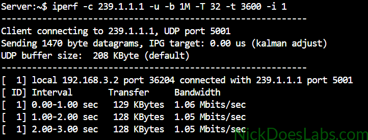
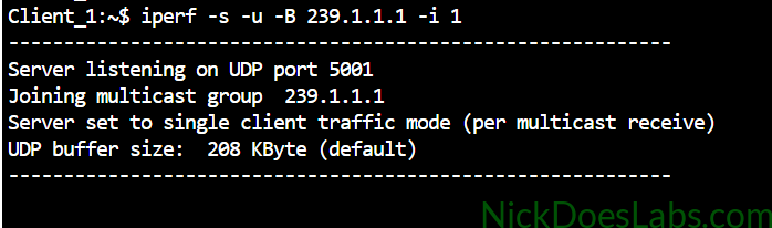
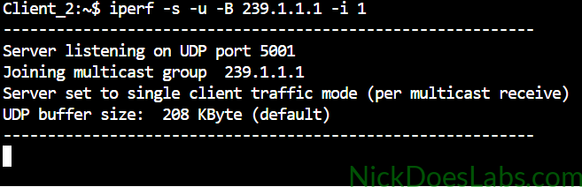
We should see traffic begin to reach the clients once we have properly configured multicast on the routers.
Step 3 – Configuring Multicast – PIM Sparse Mode
First, we need to enable multicast on all routers with the ip multicast-routing command. Then, we need to enable PIM on all interfaces that will carry multicast traffic using the ip pim sparse-mode command. PIM Sparse Mode uses a receiver-driven model instead of the flood-and-prune behavior used by Dense Mode. When a receiver joins a group, its last-hop1 router initially builds a shared tree toward the Rendezvous Point (RP). After traffic begins flowing, the last-hop router can switch to a source-based Shortest Path Tree (SPT) toward the multicast source. This process relies on a Rendezvous Point (RP). We will discuss the RP router in the next step.
We will run the following commands on all routers to enable multicast routing and PIM sparse mode.
conf t
ip multicast-routing
int gi0/0
  ip pim sparse-mode
int gi0/1
  ip pim sparse-mode
int gi0/2
  ip pim sparse-mode
int Lo0
  ip pim sparse-mode
end
wr mem
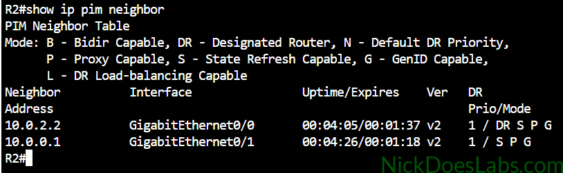
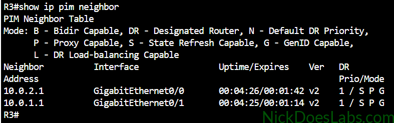
Next, we will verify that the routers have formed PIM neighborships. PIM neighborships allow routers to exchange hop-by-hop PIM control messages such as Join and Prune messages. We will verify this with the command show ip pim neighbor.
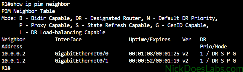
Step 4 – Configuring Multicast – RP and Bootstrap Router
In PIM Sparse Mode, the RP acts as the meeting point between multicast sources and receivers. When the server begins sending traffic, the source-side Designated Router (DR) encapsulates the initial multicast packets in PIM Register messages and sends them to the RP. When a client joins 239.1.1.1, its last-hop router sends a PIM Join toward the RP and builds (*,G) shared-tree state. After traffic begins flowing, the last-hop router can build an (S,G) Shortest Path Tree directly toward the source.
RPs can be configured statically by manually pointing each PIM-enabled router to use a specific IP address as the RP. However, this isn’t scalable so we will be using Bootstrap Router (BSR) to select an RP automatically. In the BSR protocol, we can configure candidate BSRs and candidate RPs. There is an election process based on priority or highest IP address to select the BSR. The BSR then distributes the candidate RP information throughout the PIM domain, allowing each PIM router to determine the RP for a multicast group.
For this lab I am keeping the RP and BSR roles on R1 to keep the design simple. I will use Loopback 0 for both roles because the loopback provides a stable address that remains independent of any single physical interface. This is done with the commands ip pim bsr-candidate [interface] and ip pim rp-candidate [interface] respectively.
The BSR configuration for R1 is as follows:
conf t
ip pim bsr-candidate Lo0
ip pim rp-candidate Lo0
end
wr mem
At this point multicast traffic should begin flowing to our clients.
Step 5 – Verifying Multicast
Clients 1 and 2 should now look like this:
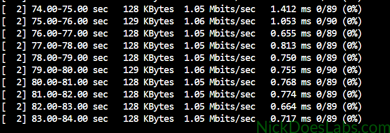
This data shows the transfer size, bandwidth, and jitter of the received multicast traffic for each one-second interval.
On R2 and R3 we can run show ip igmp groups 239.1.1.1 to verify that we see the client assigned to the group. I’ll also run show ip pim rp and show ip pim bsr to verify the RP and BSR.
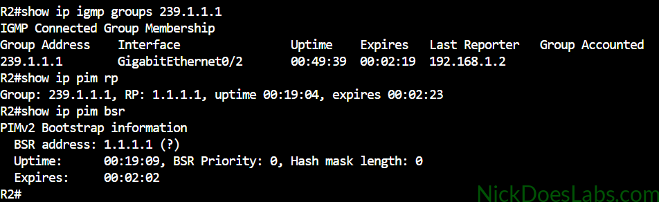
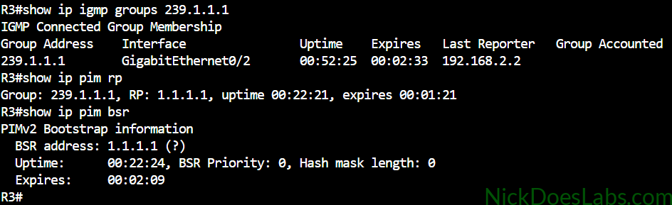
Here we see that R2 and R3 learned IGMP membership for 239.1.1.1 from their directly connected clients. We did not need a separate command to enable basic IGMP operation on these interfaces because Cisco IOS enables IGMP when PIM is configured on an interface. In this lab the clients use IGMP to tell their local router that they want to receive traffic for the multicast group.
Next, let’s look at our multicast routing table entries for 239.1.1.1:
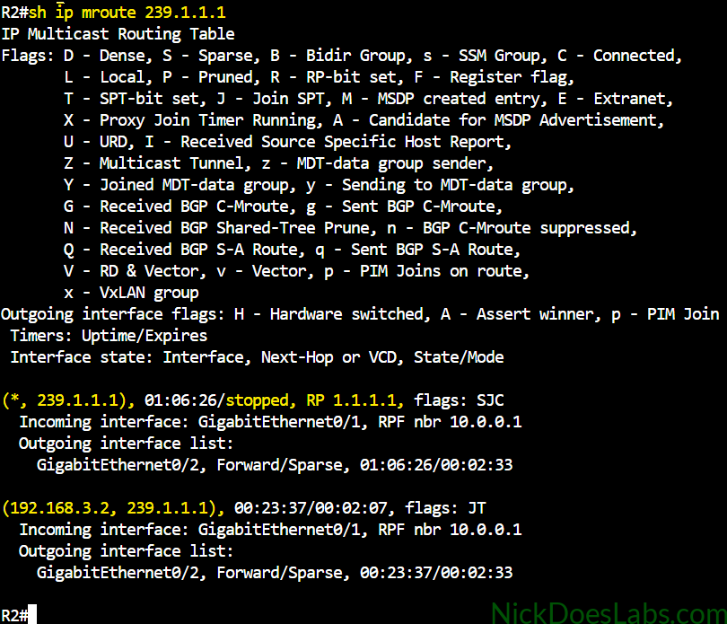
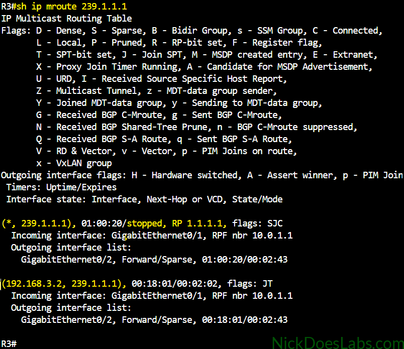
Here we can see both the (*,G) and the (S,G) entries for 239.1.1.1. The (*,G) entry represents the shared tree for all sources sending to the multicast group. This is used for the shared tree when the client first joins the group. You can see that the RP is specified because the shared tree is rooted at the RP.
The (S,G) entry is for the source tree. Once the source tree is constructed, the router now knows the source of the multicast group. In the source tree, traffic flows following the IGP shortest path.
Conclusion
In this lab we successfully configured multicast routing on Cisco IOSv in Cisco Modeling Labs. We built a topology to simulate an enterprise network with two offices and a data center connected through a WAN with OSPF as the IGP. Then, we used iPerf to simulate sending multicast traffic from one server to two clients. Next, we enabled multicast routing and PIM on all routers. Finally, we configured BSR to make R1 the BSR and RP for the network. We were able to verify multicast traffic flowing from server to client and observe valid mroutes on the routers.
The completed configuration files and lab.yaml can be downloaded here: Multicast_Lab.
- In the context of multicast, the Last Hop Router (LHR) is the gateway router closest to the receiver. ↩︎