
Overview
In this lab we will configure MPLS Traffic Engineering with RSVP-TE on IOS XRd in Cisco Modeling Labs and create tunnels for customer Layer 3 VPN traffic. RSVP-TE (Resource Reservation Protocol – Traffic Engineering) is a tool which allows engineers to create MPLS tunnels between routers with bandwidth reservations. RSVP-TE allows bandwidth requirements to be considered when establishing a Label Switched Path (LSP), making it useful when traffic engineering decisions need to account for available capacity. In addition to bandwidth reservation, it supports path engineering which allows us to control which path traffic takes through our MPLS core.
Scenario
We are providing Layer 3 VPN services to two customers, Customer A and Customer B. Per our Service Level Agreements (SLAs), Customer A should have a 50 Mbps VPN and Customer B should have a 100 Mbps VPN. Traffic is currently flowing according to the IS-IS best path, leaving some links on our network underutilized. Additionally, we currently have no bandwidth reservation mechanism to account for our SLA requirements. To account for these bandwidth requirements, we will create an MPLS tunnel for each customer using RSVP-TE. To maximize efficient utilization of our core resources, each tunnel will take a different path through our network.
Method
Cisco does not support RSVP-TE over unnumbered links, so first we will assign IP addresses to all core links. We will then configure IS-IS to support MPLS traffic engineering before enabling RSVP-TE and MPLS traffic engineering on the core interfaces. Next, we will define explicit paths between PE-1 and PE-2, create the tunnels, and steer customer traffic into them. We will use routing tables, traceroutes, and MPLS forwarding counters to verify the resulting traffic paths.
Equipment
I’ll be starting with the topology I built in my Layer 3 MPLS VPN lab. If you’d like to follow along, you can download the Layer 3 MPLS VPN CML topology and router configurations.
- Customer Edge Routers (IOSv)
- CE-1A
- CE-1B
- CE-2A
- CE-2B
- Provider Edge Routers (XRd)
- PE-1
- PE-2
- Provider Core Routers (XRd)
- P1
- P2
Prequel – How Traffic Flows Without RSVP-TE
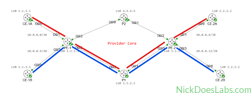
Without RSVP-TE, traffic uses the IS-IS best path available in the routing table. This means that all traffic will follow the path IS-IS chooses through the network. Currently, IS-IS is using the PE-1 > P1 > PE-2 path.
We can verify this by running traceroutes from CE-1A to CE-2A and CE-1B to CE-2B.
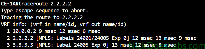
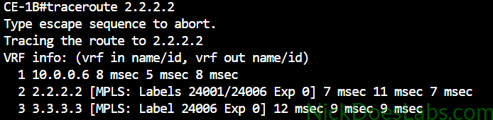
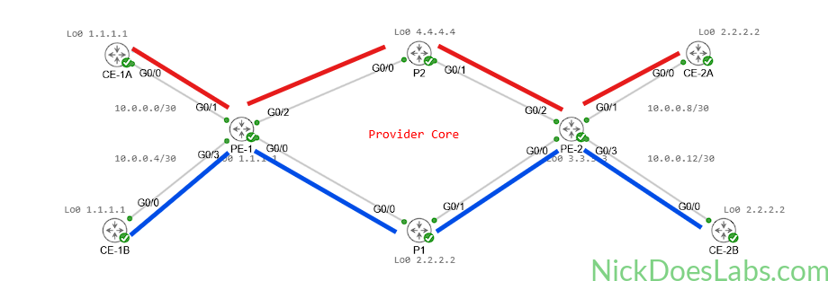
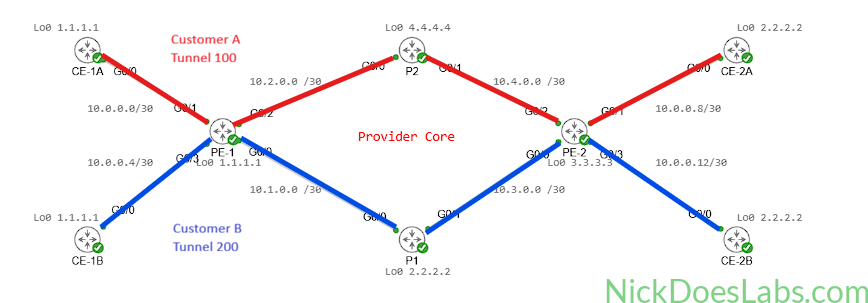
This leaves the PE-1 > P2 > PE-2 path underutilized while all customer traffic is concentrated on the path through P1. Our goal is to distribute customer traffic across both core paths so that we can make better use of the available network resources, as shown below.
Step 1 – Configuring IP Addresses on Core Links
In order for RSVP to work properly, we need IP Addresses on all links in the core. I’ll remove the ipv4 unnumbered setting and use /30 subnets between each router. I’ll assign the IP addresses as follows:
| Router | Interface | IP Address | Network |
|---|---|---|---|
| PE-1 | Gi0/0/0/0 | 10.1.0.1 | 10.1.0.0 /30 |
| PE-1 | Gi0/0/0/2 | 10.2.0.1 | 10.2.0.0 /30 |
| P1 | Gi0/0/0/0 | 10.1.0.2 | 10.1.0.0 /30 |
| P1 | Gi0/0/0/1 | 10.3.0.1 | 10.3.0.0 /30 |
| P2 | Gi0/0/0/0 | 10.2.0.2 | 10.2.0.0 /30 |
| P2 | Gi0/0/0/1 | 10.4.0.1 | 10.4.0.0 /30 |
| PE-2 | Gi0/0/0/0 | 10.3.0.2 | 10.3.0.0 /30 |
| PE-2 | Gi0/0/0/2 | 10.4.0.2 | 10.4.0.0 /30 |
Here’s the updated topology showing the network addresses used on the core links:
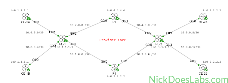
With IP addresses on all of the core-facing interfaces, we can now begin to configure IS-IS for RSVP-TE.
Step 2 – Configuring IS-IS for MPLS Traffic Engineering
We will need to configure IS-IS to use the wide metric style. Wide metrics allow IS-IS to carry additional attributes beyond standard routing information. These attributes include traffic engineering information like available bandwidth. For more information on wide metrics, see the Juniper IS-IS user guide.
We also need to explicitly enable MPLS traffic engineering in our IS-IS process. We will specify a router id to be used for traffic engineering. In this case we will simply use the loopback 0 interface as the router id. Finally, we need to tell IS-IS which levels it should advertise traffic engineering information on. The options are level 1 only, level 2 only, or both. Since our routers are all operating in L1/L2 mode by default, we will enable traffic engineering on both.
On each core router we will run the following commands to configure IS-IS for traffic engineering:
router isis CORE
  address-family ipv4 unicast
    metric-style wide
    mpls traffic-eng router-id Lo0
    mpls traffic-eng level-1-2
Now that IS-IS is configured to advertise traffic engineering information, we can move on to enabling MPLS Traffic Engineering.
Step 3 – Enabling MPLS Traffic Engineering
MPLS traffic engineering must be enabled for each interface that we want to use it on. This is straightforward on IOS XR, we simply enter MPLS traffic engineering configuration mode and specify the interfaces to enable it on.
Here are the commands for enabling MPLS-TE on all core routers:
!!! PE-1 and PE-2 !!!
mpls traffic-eng
  interface gi0/0/0/0
  interface gi0/0/0/2
!!! P1 and P2 !!!
mpls traffic-eng
interface gi0/0/0/0
interface gi0/0/0/1Step 4 – Configuring RSVP Bandwidth on MPLS Interfaces
Our next step is to configure the RSVP reservable bandwidth on all of our core MPLS interfaces. On IOS XR, we must first enter RSVP configuration mode with rsvp. Then we will enter RSVP interface configuration mode for each interface we want RSVP to operate on. Here, we need to tell RSVP how much of the interface’s bandwidth it is allowed to reserve for tunnels. I’ll be using 75%, which limits RSVP reservations to 75% of the interface bandwidth and leaves the remaining bandwidth unavailable for RSVP reservations.
Here are the commands for configuring RSVP bandwidth on all core routers:
!!! PE-1 and PE-2 !!!
rsvp
  interface gi0/0/0/0
    bandwidth percentage 75
  interface gi0/0/0/2
    bandwidth percentage 75
!!! P1 and P2 !!!
rsvp
interface gi0/0/0/0
bandwidth percentage 75
interface gi0/0/0/1
bandwidth percentage 75With RSVP and MPLS-TE enabled we can now create our tunnels.
Step 5 – Creating the Explicit Paths
Our first step in creating RSVP-TE tunnels is to define explicit paths. These paths will identify which routers the tunnels will travel through and the order that they will travel through them. The router where traffic enters the tunnel is also known as the ingress router or the headend router. The router where traffic exits the tunnel is also known as the egress router or the tailend router.
RSVP-TE tunnels only need to be configured on the headend router. The RSVP protocol will tell the rest of the routers about the tunnel, and they will reserve resources accordingly. Tunnels are unidirectional by nature, meaning that they only affect traffic flowing from headend to tailend. If we want return traffic to flow through the same path then we need to create an opposite tunnel on the tailend.
Therefore, we will need to create four explicit paths. Two paths will route Customer A traffic back and forth along the top half of the core via P2. The other two paths will route Customer B traffic back and forth through the bottom half of the core via P1. Here is a visual reminder of the traffic flow we are planning:
Explicit paths are configured by entering explicit path configuration mode in IOS XR. Once there, we will describe the path using the format index [index] next-address [IP Address]. The index number defines the order in which traffic flows through the routers. Traffic follows the path from the lowest index to the highest. We will use increments of 10 for index numbers.
The full configurations for all four explicit paths are as follows:
!!! PE-1 !!!
explicit-path name PE2_VIA_P2
  index 10 next-address 10.2.0.2
  index 20 next-address 10.4.0.2
explicit-path name PE2_VIA_P1
  index 10 next-address 10.1.0.2
  index 20 next-address 10.3.0.2
!!! PE-2 !!!
explicit-path name PE1_VIA_P2
index 10 next-address 10.4.0.1
index 20 next-address 10.2.0.1
explicit-path name PE1_VIA_P1
index 10 next-address 10.3.0.1
index 20 next-address 10.1.0.1With the paths created, we can now move on to creating the tunnels themselves.
Step 6 – Creating the RSVP-TE Tunnel Interfaces
A tunnel manifests as an interface in IOS XR. There are various types of tunnels so we need to specify that we are creating a traffic engineering tunnel with the -te suffix. For Customer A’s traffic I’ll use the interface name tunnel-te100 and for Customer B I’ll use tunnel-te200. In interface configuration mode for the tunnel we will configure the IP Address, destination, explicit path, and bandwidth reservation requirement.
The tunnel interfaces will use the router’s loopback IP address. Tunnel 100 will reserve 50 Mbps for Customer A, while tunnel 200 will reserve 100 Mbps for Customer B.
All put together, the tunnel configurations are as follows:
!!! PE-1 !!!
interface tunnel-te100
  description Tunnel for Customer A L3VPN
  ipv4 unnumbered Loopback0
  destination 3.3.3.3

  path-option 10 explicit name PE2_VIA_P2

  bandwidth 50000
!
interface tunnel-te200
  description Tunnel for Customer B L3VPN
  ipv4 unnumbered Loopback0
  destination 3.3.3.3

  path-option 10 explicit name PE2_VIA_P1

  bandwidth 100000
!!! PE-2 !!!
interface tunnel-te100
description Tunnel for Customer A L3VPN
ipv4 unnumbered Loopback0
destination 1.1.1.1
path-option 10 explicit name PE1_VIA_P2
bandwidth 50000
!
interface tunnel-te200
description Tunnel for Customer B L3VPN
ipv4 unnumbered Loopback0
destination 1.1.1.1
path-option 10 explicit name PE1_VIA_P1
bandwidth 100000We can quickly verify all four tunnels with one command on PE-1, show mpls traffic-eng tunnels brief:
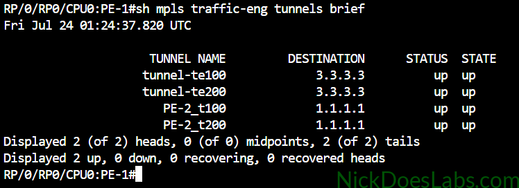
The top two tunnels are the tunnels originating on PE-1 and the bottom two are the tunnels originating on PE-2.
In future labs, I’ll cover tunnel protection, alternate path options, and RSVP-TE failover behavior.
Next, we need to steer Customer A’s traffic into tunnel 100 and Customer B’s traffic into tunnel 200.
Step 7 – Steering Traffic into RSVP-TE Tunnels
There are a few different ways to implement per-VRF traffic steering on IOS XR. Typically for this scenario the best option is Service Path Preference (SPP). Service Path Preference is built specifically for traffic engineering L3VPN services. It uses a forward class attribute that can be applied to customer routes via route policies. Traffic will then flow through the tunnel with the matching forward class.
However, forward classes are not supported on IOS XRd. Therefore, we are going to use some creativity and leverage BGP Next-Hop Recursion to accomplish our goal. This means I’m going to install two artificial routes in the routing table, one pointing to each tunnel. Then, I’ll use a BGP import policy to make each VRF use a separate artificial route as its next-hop. Therefore, each VRF’s traffic will be steered into a separate tunnel.
I’ll use the following scheme for the static routes:
| Prefix | Next Hop |
|---|---|
| 10.0.0.100 /32 | tunnel-te100 |
| 10.0.0.200 /32 | tunnel-te200 |
Then, I’ll create the following policies:
| Policy Name | BGP Next-Hop | Apply to VRF |
|---|---|---|
| TE_TUNNEL_100 | 10.0.0.100 | CUSTOMER_A |
| TE_TUNNEL_200 | 10.0.0.200 | CUSTOMER_B |
These policies will only affect traffic on the local router so we can use the exact same configuration on both PE routers. The full configuration is as follows:
!!!!! Create the static routes !!!!!
router static
 address-family ipv4 unicast
  10.0.0.100/32 tunnel-te100
  10.0.0.200/32 tunnel-te200

!!!!! Create the policies !!!!!
route-policy TE_TUNNEL_100
 set next-hop 10.0.0.100
 pass
end-policy
route-policy TE_TUNNEL_200
 set next-hop 10.0.0.200
 pass
end-policy

!!!!! Apply the policies !!!!!
vrf CUSTOMER_A
 address-family ipv4 unicast
  import route-policy TE_TUNNEL_100
vrf CUSTOMER_B
 address-family ipv4 unicast
  import route-policy TE_TUNNEL_200
Now, at this point I received the following error:
RP/0/RP0/CPU0:PE-1#RP/0/RP0/CPU0:Jul 25 16:57:05.170 UTC: bgp[1084]: %ROUTING-BGP-4-SAME_RD_SET : Ignored import policy set operation for same RD import on 2.2.2.2/32 path received from 3.3.3.3
This is IOS XR’s way of saying it doesn’t like the fact that we have the same RD on both PE routers. This exposes a major flaw in my Layer 3 VPN design. I should have designed it with per-PE route distinguishers from the start since they cannot be changed while the VRF is active. Unfortunately, this means that we now need to rebuild the VRF which would cause a service outage in the real world. This is the perfect example of why it is important to practice things in a lab environment first.
Anyway, here are the commands we need to run to fix this:
!!!!! PE-1 !!!!!

!!!!! Remove the Address Family !!!!!
vrf CUSTOMER_A
 no address-family ipv4 unicast
vrf CUSTOMER_B
 no address-family ipv4 unicast
router bgp 500
  vrf CUSTOMER_A
    no address-family ipv4 unicast
  vrf CUSTOMER_B
    no address-family ipv4 unicast
commit
end

!!!!! Change the RD !!!!!!
config
vrf CUSTOMER_A
 no rd
 rd 1.1.1.1:1
!
vrf CUSTOMER_B
 no rd
 rd 1.1.1.1:2
!
commit

!!!!! Rebuild the Address Family !!!!!
vrf CUSTOMER_A
 address-family ipv4 unicast
  import route-policy TE_TUNNEL_100
  import route-target
   100:100
  !
  export route-target
   100:100
vrf CUSTOMER_B
 address-family ipv4 unicast
  import route-policy TE_TUNNEL_200
  import route-target
   200:200
  !
  export route-target
   200:200
router bgp 500
  vrf CUSTOMER_A
    address-family ipv4 unicast
      redistribute ospf CUSTOMER_A
  vrf CUSTOMER_B
    address-family ipv4 unicast
      redistribute ospf CUSTOMER_B
commit
!!!!! PE-2 !!!!!
!!!!! Remove the Address Family !!!!!
vrf CUSTOMER_A
no address-family ipv4 unicast
vrf CUSTOMER_B
no address-family ipv4 unicast
router bgp 500
vrf CUSTOMER_A
no address-family ipv4 unicast
vrf CUSTOMER_B
no address-family ipv4 unicast
commit
end
!!!!! Change the RD !!!!!!
config
vrf CUSTOMER_A
no rd
rd 3.3.3.3:1
!
vrf CUSTOMER_B
no rd
rd 3.3.3.3:2
!
commit
!!!!! Rebuild the Address Family !!!!!
vrf CUSTOMER_A
address-family ipv4 unicast
import route-policy TE_TUNNEL_100
import route-target
100:100
!
export route-target
100:100
vrf CUSTOMER_B
address-family ipv4 unicast
import route-policy TE_TUNNEL_200
import route-target
200:200
!
export route-target
200:200
router bgp 500
vrf CUSTOMER_A
address-family ipv4 unicast
redistribute ospf CUSTOMER_A
vrf CUSTOMER_B
address-family ipv4 unicast
redistribute ospf CUSTOMER_B
commitAt this point, traffic steering should be implemented and our L3VPN traffic should be using the appropriate tunnels.
Step 8 – Verifying RSVP-TE and Traffic Steering
Let’s start by verifying that our BGP next-hop recursion is steering our traffic properly in the control plane. I’ll look at the routing tables to confirm that traffic is being routed to the RSVP tunnels.
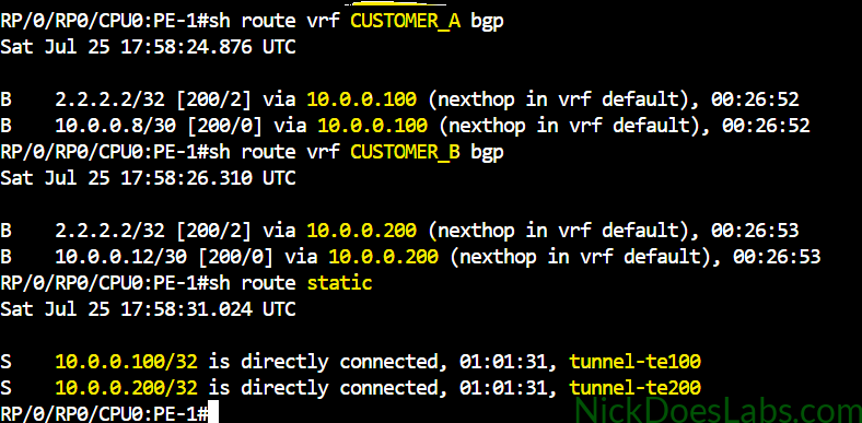
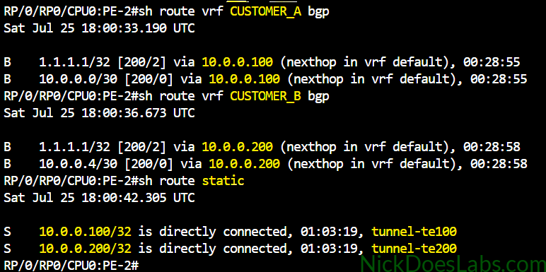
BGP next-hop recursion is successfully steering Customer A traffic into tunnel 100 and Customer B traffic into tunnel 200.
Next, let’s verify that our tunnels appear in the MPLS forwarding table:
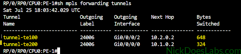
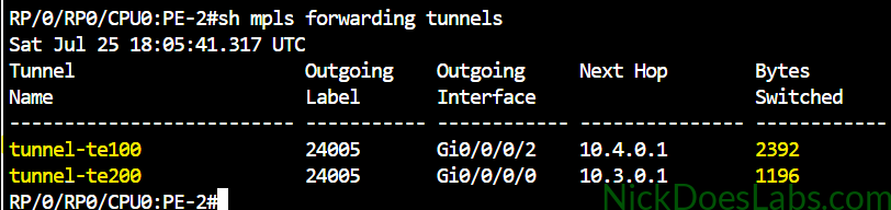
Keep an eye on the bytes switched counters. We’ll use them to verify that traffic is actually using the tunnels.
Next, I’ll run traceroutes across the Layer 3 VPN:
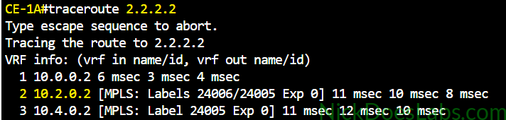
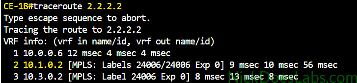
Customer A traffic is traveling through P2 at 10.2.0.2 and Customer B traffic is traveling through P1 at 10.1.0.2. This matches our intended traffic flow.
Finally, let’s confirm that the byte counters increased from the traceroutes:
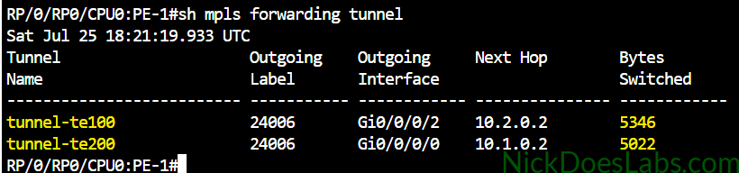
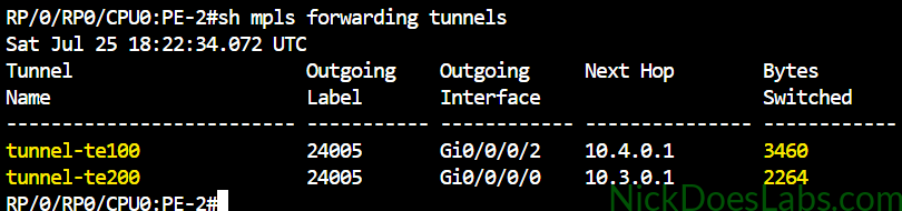
The bytes switched counters increased for both tunnels, confirming that traffic is using the traffic-engineered paths in the data plane.
Conclusion
In this lab, we used RSVP-TE to engineer separate paths through our MPLS core instead of allowing all customer traffic to follow the IS-IS best path through P1. We configured MPLS Traffic Engineering and RSVP, created explicit paths and TE tunnels, and used BGP next-hop recursion with VRF import route policies to steer each customer into the appropriate tunnel. We then verified that the tunnels were established and that each customer’s traffic was following the intended path through the core. This gives us more control over how customer traffic flows through the MPLS core while allowing bandwidth requirements to be considered during RSVP-TE tunnel establishment.
The complete lab.yaml file and router configuration files are available for download here: RSVP-TE_IOS_XRd.