
Overview
In this lab, we will configure a multipoint Layer 2 VPN using EVPN over MPLS. EVPN is one protocol which can be used to implement the MEF E-LAN standard. EVPN accomplishes the same function as VPLS, except it implements it in a more modern and efficient way. Traditional VPLS commonly uses a full mesh of pseudowires between the PE routers participating in a VPLS instance. EVPN replaces this pseudowire signaling model by using MP-BGP to advertise MAC reachability between PE routers. When a frame arrives on the customer-facing interface, or attachment circuit, the PE router will look up the destination MAC address in its MAC forwarding table and forward the frame across the MPLS data plane toward the appropriate PE router. Therefore, EVPN reduces complexity and overhead in the control plane compared to VPLS.
Scenario
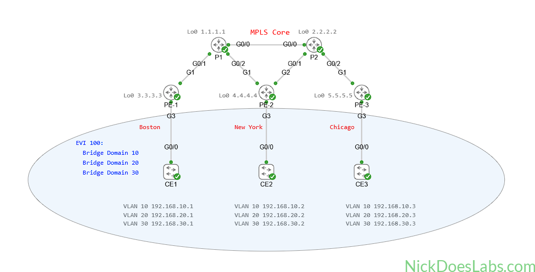
A customer has requested a multipoint Layer 2 VPN from their service provider. The customer has three sites spread across three different cities.
Method
First we will configure an EVPN Instance (EVI) on each PE router. Then, we will configure service instances on each attachment circuit. Next, we will configure the bridge domain and connect the attachment circuits to it. Finally, we will configure MP-BGP for EVPN. We will verify MAC learning on the PE routers, as well as layer 2 adjacency between all three CE switches.
Equipment
We will start with a fully functioning service provider core with three CSR1000v PE routers and two IOS XRd P routers. I’m using CSR1000v for the PE routers due to an issue with the IOS XRd data plane on multipoint layer 2 VPNs. I’ve kept this topology small since CSR1000v is resource-heavy compared to the containerized IOS XRd.
If you’d like to import the starting topology into Cisco Modeling Labs to follow along, you can download it here: CSR1000v Provider Core. If you are building this yourself, make sure that you enable node staging and stagger the node priorities to avoid overwhelming your Cisco Modeling Labs host.
- Customer Edge Switches (IOSvL2)
- CE-1
- CE-2
- CE-3
- Provider Edge Routers (CSR1000v)
- PE-1
- PE-2
- PE-3
- Provider Core Routers (XRd)
- P1
- P2
Step 1 – Adding the Customer Equipment
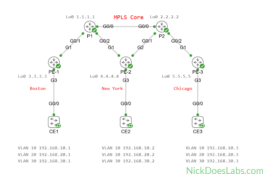
We’ll add three IOSvL2 switch nodes to the topology, one for each PE router. The G0/0 port of each CE switch will be configured as a trunk and connected to the G3 port of the local PE router.
The switches will be configured as follows:
| Hostname | VLAN 10 IP | VLAN 20 IP | VLAN 30 IP |
|---|---|---|---|
| CE-1 | 192.168.10.1 | 192.168.20.1 | 192.168.30.1 |
| CE-2 | 192.168.10.2 | 192.168.20.2 | 192.168.30.2 |
| CE-3 | 192.168.10.3 | 192.168.20.3 | 192.168.30.3 |
This gives us the following topology:
Step 2 – Enabling EVPN and Configuring the EVPN Instance
First, we need to enable EVPN globally on each PE router with the command l2vpn evpn. We also need to enable ingress replication, which allows the router to deliver Broadcast, Unknown Unicast, and Multicast (BUM) traffic to the other PE routers. Finally, we will assign a router ID to be used for EVPN. We will use the Loopback0 IP address for the router ID.
Therefore, to enable EVPN on all PE routers we will run the following commands:
l2vpn evpn
  replication-type ingress
  router-id Lo0
Next, we will configure an EVPN Instance (EVI) for the customer. We will give them the EVI number 100. There are three different types of EVPN architectures, VLAN-Based, VLAN-Bundled, and VLAN-Aware. The differences between the three service models are summarized in the following table:
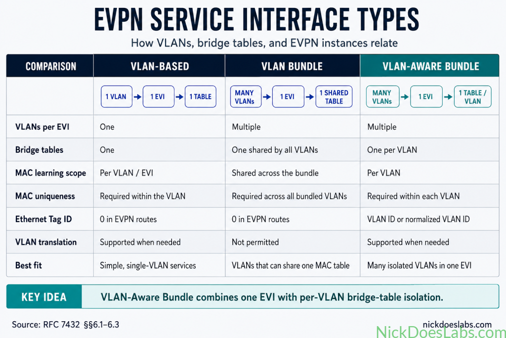
I want the customer to be able to send multiple VLANs across their EVPN instance. Also, I want those VLANs to have separate MAC address tables to avoid conflicts. Therefore, a VLAN-aware bundle is the best choice, and that is what we will implement.
To create the VLAN-Aware EVI on each PE router we will run the following command:
l2vpn evpn instance 100 vlan-awareLike VRFs in Layer 3 VPNs, EVIs also have route distinguishers and route targets. IOS XE will automatically generate them since we aren’t defining them explicitly.
Next, we will configure a service instance for the customer on the customer-facing interface. The customer-facing interface in a Layer 2 VPN is formally known as the attachment circuit.
Step 3 – Configuring the EVPN Attachment Circuits
For each attachment circuit we will need to configure three service instances. Each service instance will classify traffic for a specific customer VLAN on the attachment circuit. In the next step, we will associate the service instance with a bridge domain and EVI 100. In service instance configuration mode we will also specify the encapsulation type and VLAN number for each VLAN.
The full attachment circuit configuration for all PE routers is as follows:
interface Gi3
  no shutdown
  service instance 10 ethernet
    encapsulation dot1q 10
  service instance 20 ethernet
    encapsulation dot1q 20
  service instance 30 ethernet
    encapsulation dot1q 30
With the attachment circuits configured, we can now configure the bridge domains.
Step 4 – Configuring EVPN Bridge Domains
A bridge domain in a multipoint layer 2 VPN acts as a virtual switch. Its job is to learn MAC addresses and forward frames toward the relevant local attachment circuit or remote PE router. Bridge Domains are also used in VPLS, in which they are connected via pseudowires. In EVPN, MP-BGP advertises the reachability and label information needed to connect matching bridge domains across the MPLS data plane. In a VLAN aware EVPN, each VLAN gets its own bridge domain.
To create a bridge domain on IOS XE, we will use the command bridge-domain [number]. For simplicity, I’ll correlate our bridge domain numbers with our service instance numbers. For each bridge domain we will bind the service instance and EVPN instance that it correlates to with the member command. When we bind a bridge domain to a VLAN-aware EVPN instance, we also tell the router which Ethernet Tag to use for that bridge domain. In this lab, I will match the Ethernet Tag, bridge-domain number, service-instance number, and VLAN ID to keep the configuration easy to follow.
The complete bridge domain configuration on each PE router is as follows:
bridge-domain 10
 member evpn-instance 100 ethernet-tag 10
 member Gi3 service-instance 10
bridge-domain 20
 member evpn-instance 100 ethernet-tag 20
 member Gi3 service-instance 20
bridge-domain 30
 member evpn-instance 100 ethernet-tag 30
 member Gi3 service-instance 30
With our bridge domains created on each PE router, we can now use MP-BGP to advertise EVPN reachability between the PE routers.
Step 5 – Configuring BGP for EVPN
As I mentioned in the previous section, EVPN uses Multiprotocol BGP rather than VPLS pseudowire signaling to exchange reachability information between PE routers. BGP includes an L2VPN EVPN address family for these routes. We simply need to configure this address family on each PE router and establish BGP neighbor sessions between them. In the real world a Route Reflector would be used in this scenario. However, since we only have three PE routers I’ll just use full-mesh iBGP peering.
The EVPN BGP configurations for each PE router are as follows:
!!! PE-1 !!!
router bgp 500
  neighbor 4.4.4.4 remote-as 500
  neighbor 5.5.5.5 remote-as 500
  neighbor 4.4.4.4 update-source Lo0
  neighbor 5.5.5.5 update-source Lo0
  address-family l2vpn evpn
    neighbor 4.4.4.4 activate
    neighbor 5.5.5.5 activate
    neighbor 4.4.4.4 send-community both
    neighbor 5.5.5.5 send-community both
!!! PE-2 !!!
router bgp 500
neighbor 3.3.3.3 remote-as 500
neighbor 5.5.5.5 remote-as 500
neighbor 3.3.3.3 update-source Lo0
neighbor 5.5.5.5 update-source Lo0
address-family l2vpn evpn
neighbor 3.3.3.3 activate
neighbor 5.5.5.5 activate
neighbor 3.3.3.3 send-community both
neighbor 5.5.5.5 send-community both!!! PE-3 !!!
router bgp 500
neighbor 3.3.3.3 remote-as 500
neighbor 4.4.4.4 remote-as 500
neighbor 3.3.3.3 update-source Lo0
neighbor 4.4.4.4 update-source Lo0
address-family l2vpn evpn
neighbor 3.3.3.3 activate
neighbor 4.4.4.4 activate
neighbor 3.3.3.3 send-community both
neighbor 4.4.4.4 send-community bothThe send-community both command ensures that we send both the standard and extended BGP communities to the neighboring PE routers. This is important because the Route Target is carried as a BGP extended community.
Now that our BGP EVPN neighbor sessions are configured, we can verify that EVPN is working.
Step 6 – Verifying EVPN
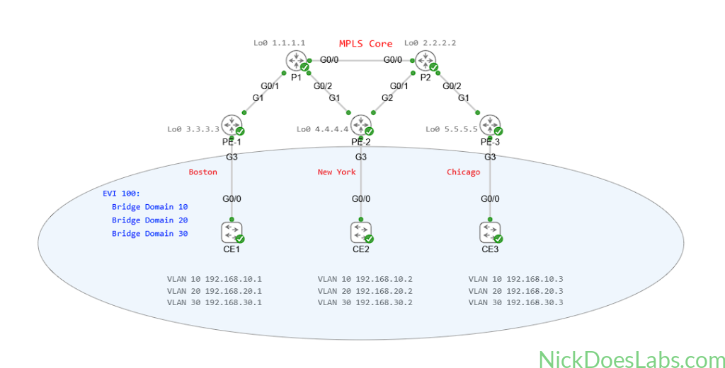
First, we can verify our BGP EVPN peering with the command show bgp l2vpn evpn summary:
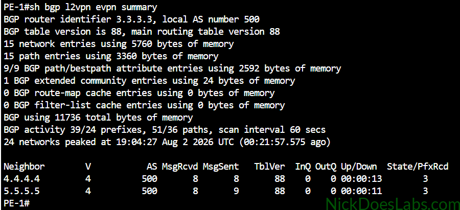
This output proves that PE-1 has successfully formed l2vpn evpn neighborships with PE-2 and PE-3, and it is receiving three prefixes from each.
Next, I’ll confirm that CE-1 can reach CE-2 and CE-3 in each VLAN with ping commands:
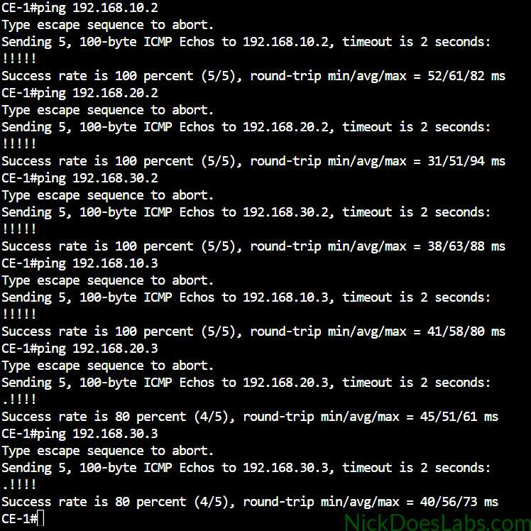
This proves that CE-1 is able to ping the corresponding SVIs on CE-2 and CE-3 for each VLAN.
Next, let’s confirm that our bridge domains are learning MAC Addresses with the show l2vpn evpn mac command:
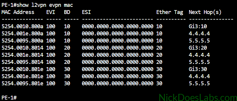
Here we see the full list of MAC addresses of each of the CE switches’ SVIs. The Next Hop column shows the interface and service instance for locally learned MACs, and the PE router for remotely learned MACs. The BD column tells us which bridge domain learned the MAC, and the Ether Tag column tells us which VLAN it corresponds to.
Finally, we can verify that EVPN over MPLS is working properly with the show mpls forwarding-table command.
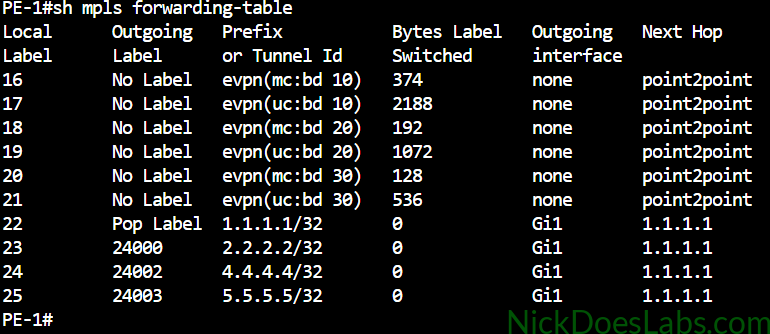
Here we can see the MPLS labels assigned for each bridge domain. Each bridge domain has two labels, one for unicast and one for Broadcast, Unknown Unicast, and Multicast traffic.
Conclusion
In this lab, we successfully configured a multipoint Layer 2 VPN or E-LAN on three PE routers running IOS XE. We created a global VLAN-aware EVI for the customer, and a service instance for each VLAN on each attachment circuit. We then created bridge domains for each VLAN and bound them to the relevant service instances and the EVI. Finally, we used MP-BGP to advertise MAC reachability between the PE routers, while MPLS carried the customer frames across the provider core. We were able to demonstrate end to end connectivity between the CE switches through the EVPN connection.
You can download the completed configuration files and lab.yaml file here: EVPN L2VPN on CSR1000v.
Note: I’m unable to add the VLANs in to the CE switch startup configurations. This is because IOS stores VLANs in a separate vlan.dat database. They need to be added manually for this lab to work.