
Overview
Quality of Service (QoS) is an essential concept for network engineers to understand. In this lab we will configure QoS Classification and Marking in a Layer 3 MPLS VPN with Cisco Modeling Labs. Even the best networks will face congestion at some point. QoS determines how packets are treated when congestion occurs, allowing us to prioritize sensitive traffic like VOIP and video. This will be the first lab in a two part series on Layer 3 QoS and congestion management. In this lab we will configure the QoS markings, but not actually change how the traffic is treated. In the next lab we will configure congestion avoidance, queuing, and policing which will use the QoS marking to prioritize sensitive traffic.
Scenario
Customer A and Customer B are Layer 3 VPN customers connected to our network. Both customers send VOIP traffic through the layer 3 VPN for internal calls between offices. Customer B also needs to send real time video through the VPN for their security cameras. We need to ensure that both customers’ VOIP traffic and Customer B’s video traffic is prioritized if congestion occurs in our MPLS core. Therefore, we need to classify and mark these traffic types. Customer B is a managed services client so we will trust QoS markings coming from the CE router. We do not manage Customer A’s CE router so we will not trust their QoS markings.
Method
For Customer A, we will configure an access list to identify VOIP traffic at the PE router. We will then create a class-map based on this access list. Then, we will apply a policy map to mark the VOIP traffic. For Customer B we will assume the traffic has already been marked appropriately and classify it based on the marking. We will use DSCP markings for both customers.
Equipment
I’ll be using the topology built in my Layer 3 MPLS VPN on CSR1000v lab which can be downloaded here: Layer 3 VPN on CSR1000v. I’ll also add four Desktop nodes (Alpine Linux) to the topology. I will use these nodes to generate dummy traffic to validate the QoS configurations.
- Customer Edge Routers (IOSv)
- CE-1A
- CE-1B
- CE-2A
- CE-2B
- Provider Edge Routers (CSR1000v)
- PE-1
- PE-2
- Provider Core Routers (CSR1000v)
- P1
- P2
- Customer Desktops (Desktop)
- CD-1A
- CD-1B
- CD-2A
- CD-2B
Step 1 – Adding the Customer Desktops
First, we’ll add four of the default Alpine Linux Desktop nodes from Cisco Modeling Labs and connect them as follows:
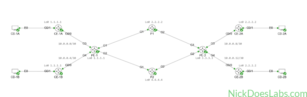
I’ll configure the following IP Addresses on the E0 interface of the Desktops:
| Desktop | E0 IP Address | Default Gateway |
|---|---|---|
| CD-1A | 192.168.1.2 /24 | 192.168.1.1 |
| CD-2A | 192.168.2.2 /24 | 192.168.2.1 |
| CD-1B | 192.168.3.2 /24 | 192.168.3.1 |
| CD-2B | 192.168.4.2 /24 | 192.168.4.1 |
I’ll then configure the G0/1 interfaces with the default gateway IP Addresses for each desktop, and advertise the subnet into OSPF. Here is an example on CE-1A:
int gi0/1
  no shutdown
  ip address 192.168.1.1 255.255.255.0
  description link to CD-1A
router ospf 1
  network 192.168.1.0 0.0.0.255 area 1
Before moving on, I’ll verify end-to-end connectivity between the customer desktops:
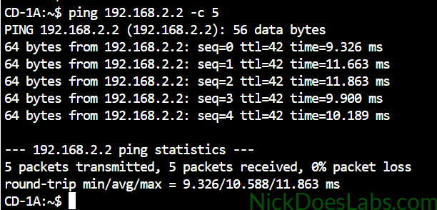
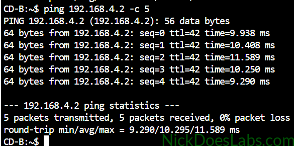
We are now ready to begin classifying traffic for QoS.
Step 2 – Configuring QoS Classification for Customer A
We do not manage Customer A’s network, so we cannot trust their QoS markings. Therefore we need to do our own classification and marking for their traffic at the PE router. The only traffic we are interested in classifying for Customer A is VOIP.
We will configure two Access Lists (ACLs) on the PE routers to match SIP signaling and UDP Voice traffic. SIP Signaling uses UDP port 5060, and TCP ports 5060/5061. VOIP traffic classically uses UDP port ranges 16384–32767. ‘
We will run the following commands on both PE routers to create the ACLs:
ip access-list extended VOIP
  permit udp any any range 16384 32767
  exit
ip access-list extended SIP
  permit udp any any eq 5060
  permit tcp any any eq 5060
  permit tcp any any eq 5061
These ACLs will allow the routers to identify VOIP and SIP traffic. Next, we need to create Class Maps which will classify the traffic.
class-map VOIP-CUST-A
  match access-group name VOIP
class-map SIP-CUST-A
  match access-group name SIP
The class map simply classifies traffic which matches the access-groups we configured. We can now implement a policy map to actually mark the traffic.
Step 3 – Configuring QoS Marking for Customer A
We need to create and apply inbound policy maps on the interfaces connecting to Customer A’s CE routers. These policy maps will mark the VOIP and SIP packets with DSCP values ef and cs3 respectively. EF stands for expedited forwarding, and it is the recommended DSCP value for VOIP traffic. CS3 stands for Class Selector 3 which is the recommended DSCP value for SIP signaling.
The commands to create and apply Customer A’s policy map are as follows for both PE routers:
policy-map VOICE-QOS-CUST-A
  class VOIP-CUST-A
    set dscp ef
  class SIP-CUST-A
    set dscp cs3
  class class-default
    set dscp default
int gi3
  service-policy input VOICE-QOS-CUST-A
Any traffic that doesn’t match the VOIP or SIP class will fall under the default class and be marked as DSCP 0 (best effort).
At this point our PE routers are properly configured to classify and mark Customer A’s VOIP and SIP traffic. We can now move on to configuring classification and marking for Customer B.
Step 4 – Configuring QoS Classification for Customer B
We are treating Customer B differently by trusting the QoS markings sent from the CE router. For the purpose of this lab we’ll assume that Customer B’s devices are doing their own DSCP marking. Therefore we just need to classify the traffic based on the DSCP markings received at the PE router.
The following commands will classify traffic as voice, video or SIP based on the DSCP marking:
class-map VOICE
  match dscp ef
class-map SIP
  match dscp cs3
class-map VIDEO
  match dscp af41
This is all that we need to do for Customer B since they are trusted to generate their own DSCP markings.
Step 5 – Verifying QoS Classification and Marking
I’ll be using iPerf to generate traffic and verify that the class maps and policy maps configured earlier are working properly.
To simulate voice transmission, I’ll use the following commands on CD-1A and CD-2A:
#CD-1A#
iperf -c 192.168.2.2 -p 17000 -u -b 1M -t 600 -l 1200

#CD-2A#
iperf -s -u -p 17000
This generates a 10 minute stream of UDP packets destined for CD-2A. The packets will match the VOIP access list and should be flagged with DSCP ef. I’ll test this by running a packet capture on the link between PE-2 and CE-2A:
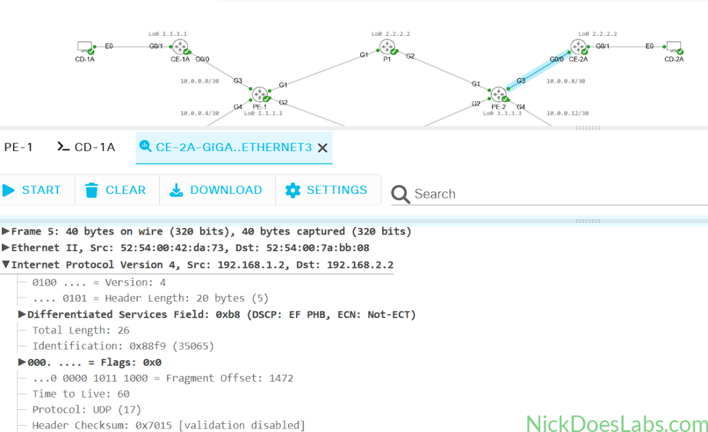
The DSCP field is properly set to EF as we expected. Next, we’ll simulate SIP signaling by changing the iPerf commands to:
#CD-1A#
iperf -c 192.168.2.2 -p 5060 -u -b 1M -t 600 -l 1200

#CD-2A#
iperf -s -u -p 5060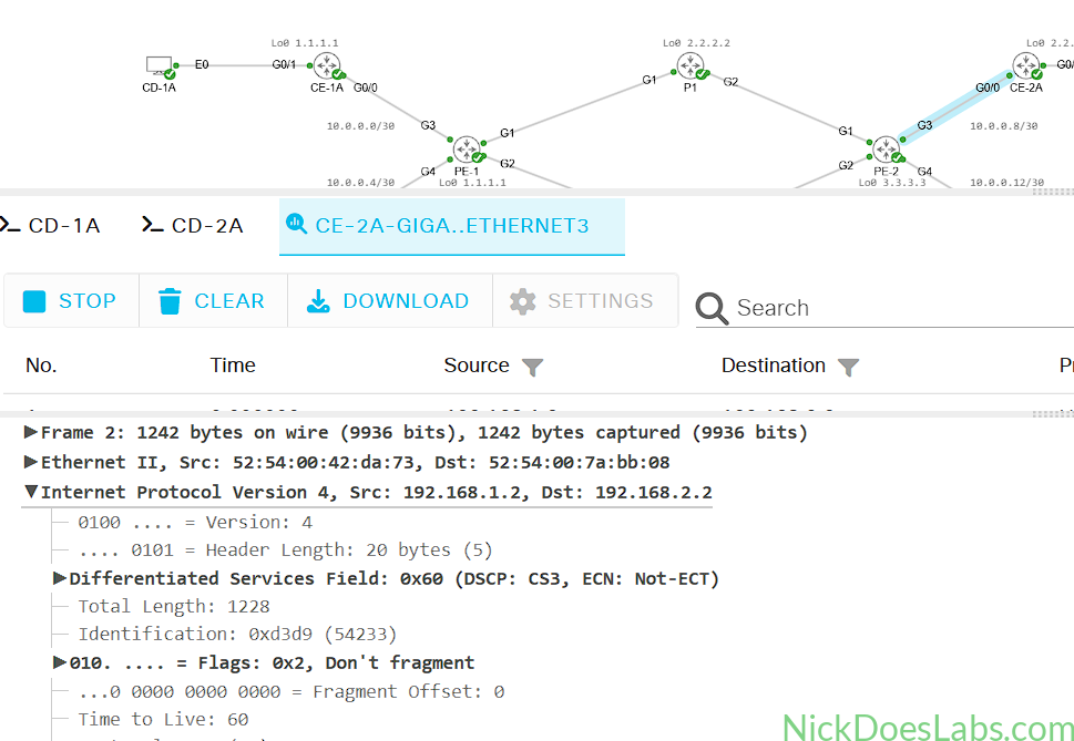
Here we see the DSCP is set to CS3 for SIP signaling traffic as expected.
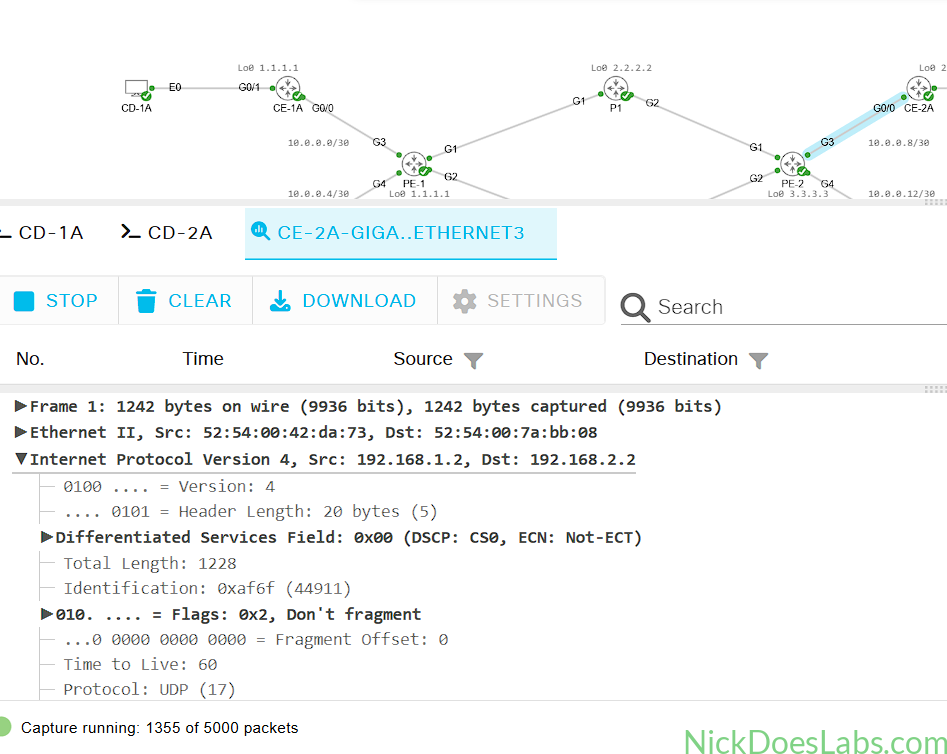
Next, we will simulate a scenario where Customer A tries to mark non-VOIP traffic as EF. Since we are doing our own classification and marking, our policy-map should re-mark it as CS0 or best effort traffic.
For this test I’ll use the following iPerf commands:
#CD-1A#
iperf -c 192.168.2.2 -p 8000 -u -b 1M -t 600 -l 1200 --dscp 46

#CD-2A#
iperf -s -u -p 8000
Since port 8000 doesn’t match the VOIP or SIP access lists, the traffic is re-marked to best-effort:
Finally, I’ll test the same scenario with Customer B’s devices. Since we are trusting Customer B and not re-marking their traffic, it should remain unchanged. I’ll run the following:
#CD-1B#
iperf -c 192.168.4.2 -p 8000 -u -b 1M -t 600 -l 1200 --dscp 46

#CD-2B#
iperf -s -u -p 8000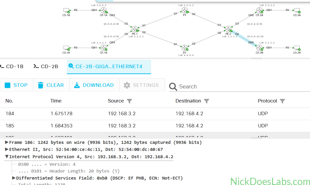
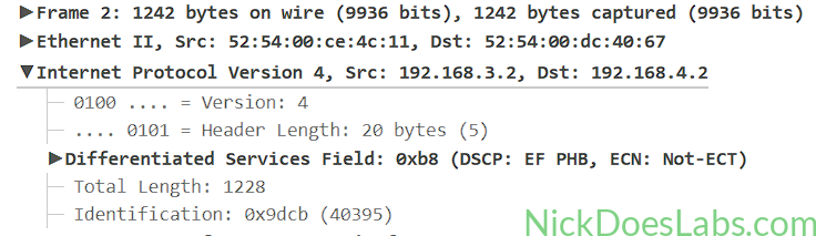
As expected, the DSCP EF tag remained unchanged throughout the L3VPN.
Conclusion
In this lab we successfully configured ACLs to identify sensitive traffic, class-maps to classify it, and policy maps to mark it. For Customer A we did our own classification and marking of traffic, ensuring that only their VOIP and SIP traffic gets QoS guarantee. However for Customer B we trusted the QoS markings generated on the customer network and simply classified traffic based on those. We then used packet captures in Cisco Modeling Labs to capture and inspect traffic generated by iPerf. We generated traffic that matched our VOIP, SIP, and default classes and confirmed they were marked EF, CS3, and CS0 respectively. In the next lab we will configure congestion management and congestion avoidance to determine how these different traffic classes are treated when the network gets overwhelmed.
The configuration files for each device as well as the lab.yaml file are available here: L3VPN_QoS.