Overview
In this lab, we will build a Layer 3 MPLS VPN that allows customer edge (CE) routers to send private traffic across our MPLS core. We will provide end-to-end connectivity between the customer sites while maintaining route separation through VRFs. This lab will use the Cisco CSR1000v (IOS XE) image for all PE and P routers. To learn how to build a Layer 3 VPN with IOS XR, see How to Build a Layer 3 MPLS VPN in Cisco Modeling Labs (IOS XR).
You can download the lab.yaml file and router configuration files to get started with here.
Scenario
Customer A and Customer B both have two sites in different cities. Both customers have requested private Layer 3 VPNs between their respective offices. Neither customer will be able to see each other’s routes, despite connecting to the same provider edge equipment.
Method
The provider edge (PE) routers will peer via OSPF with the customer edge (CE) routers and use VRFs to keep the routing tables separate. They will then use MP-BGP to share the customers’ routes with each other via VPNv4. The customer routes and traffic will transit the core via MPLS, and the provider (P) routers will not see customer routes or IP Addresses, only transport labels. The end result is that CE-1A and CE-2A can communicate with each other, and CE-1B and CE-2B can as well. However, Customer A’s routers will not be able to communicate with Customer B’s routers or see their routes and vice versa.
Equipment
- Customer Edge Routers (IOSv)
- CE-1A
- CE-1B
- CE-2A
- CE-2B
- Provider Edge Routers (CSR1000v)
- PE-1
- PE-2
- Provider Core Routers (CSR1000v)
- P1
- P2
Step 1 – Adding the Customer Routers
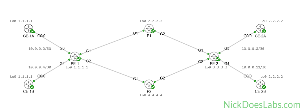
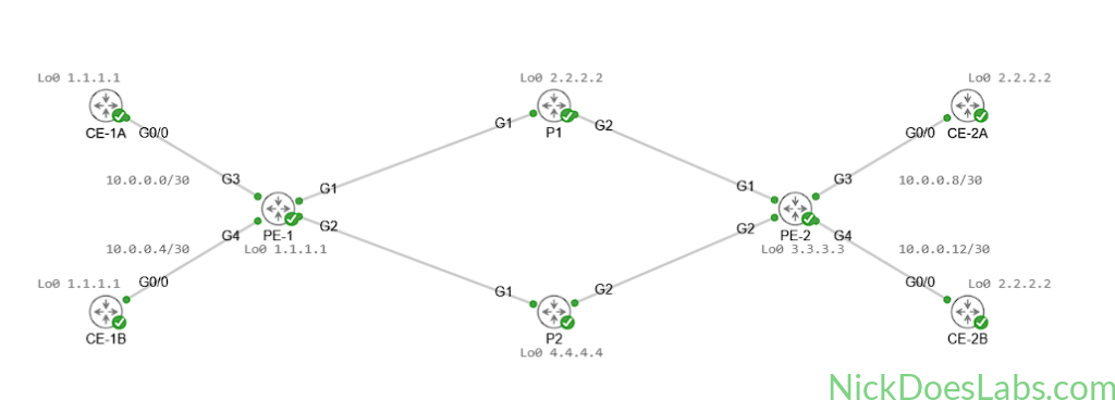
We will add four IOSv images to the topology and connect them to the provider core. CE-1A and CE-1B will connect to PE-1 and CE-2A and CE-2B will connect to PE-2. We will configure them with IP addresses on the interfaces connecting to the service provider as well as loopback addresses. I’m using /30 subnets for the CE-PE links. Because customer routes will be segregated by VRFs, it is safe to use overlapping loopback addresses as long as they are unique within the customer network.
Here’s the configuration on CE-1A:
hostname CE-1A
!
ip domain-name nickdoeslabs.com
!
interface gigabitEthernet0/0
  no shutdown
  ip address 10.0.0.1 255.255.255.252
  description link to PE-1
!
interface Loopback 0
  no shutdown
ip address 1.1.1.1 255.255.255.255| Router | Loopback | Gi0/0 |
|---|---|---|
| CE-1A | 1.1.1.1 /32 | 10.0.0.1 /30 |
| CE-1B | 1.1.1.1 /32 | 10.0.0.5 /30 |
| CE-2A | 2.2.2.2 /32 | 10.0.0.9 /30 |
| CE-2B | 2.2.2.2 /32 | 10.0.0.13 /30 |
The resulting topology looks like this:
With our CE routers configured we can now configure the customer-facing interfaces on the PE routers.
Step 2 – Basic Connectivity to the Provider Edge Routers
On the PE routers we will assign IP addresses on the links facing the customer routers. These will be assigned as follows:
| Router | G3 IP | G4 IP |
|---|---|---|
| PE-1 | 10.0.0.2 /30 | 10.0.0.6 /30 |
| PE-2 | 10.0.0.10 /30 | 10.0.0.14 /30 |
We will also create our VRFs and assign the appropriate interfaces to them. VRFs will provide a virtual routing table, keeping customer routes and traffic isolated and private. VRFs are Layer 3 tools that function similarly to VLANs at Layer 2. Layer 3 traffic and routes cannot cross between VRFs by default.
Our VRF assignments will be:
| Router | G3 VRF | G4 VRF |
|---|---|---|
| PE-1 | CUSTOMER_A | CUSTOMER_B |
| PE-2 | CUSTOMER_A | CUSTOMER_B |
For each PE router we will use the following configurations:
!!!! PE-1 !!!!!
vrf definition CUSTOMER_A
  address-family ipv4 unicast
vrf definition CUSTOMER_B
  address-family ipv4 unicast
!
int g3
  vrf forwarding CUSTOMER_A
  ip address 10.0.0.2 255.255.255.252
  no shutdown
!
int g4
  vrf forwarding CUSTOMER_B
  ip address 10.0.0.6 255.255.255.252
  no shutdown
!!!! PE-2 !!!!
vrf definition CUSTOMER_A
address-family ipv4 unicast
vrf definition CUSTOMER_B
address-family ipv4 unicast
!
int g3
vrf forwarding CUSTOMER_A
ip address 10.0.0.10 255.255.255.252
no shutdown
!
int g4
vrf forwarding CUSTOMER_B
ip address 10.0.0.14 255.255.255.252
no shutdownNote: On IOS XE the order of these commands is important. The VRF must be defined first and assigned an address family. Then, in interface configuration mode you must assign the interface to the VRF before assigning an IP and enabling the interface. Otherwise, assigning an interface to a VRF will remove the IP address and disable the interface automatically.
At this point both PE routers can ping their directly connected customer routers:
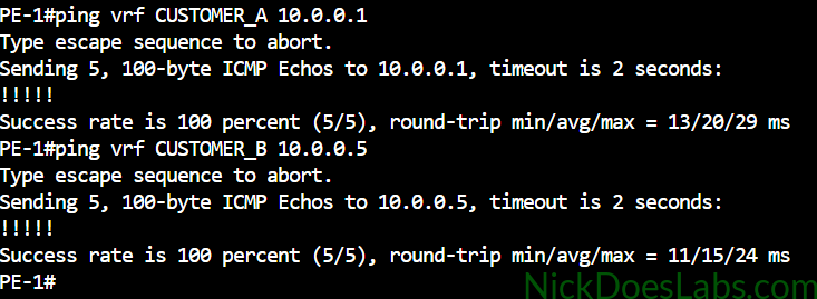
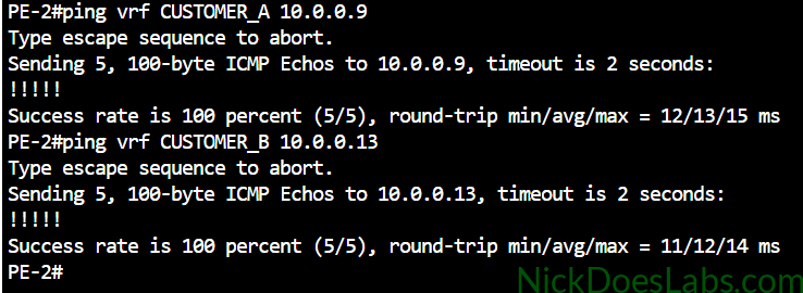
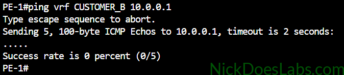
This is a good time to take note of the isolation that VRFs provide. We can only ping each customer within its respective VRF. Pinging between VRFs will fail. In this example, because the 10.0.0.1 route belongs to the CUSTOMER_A VRF, we cannot ping it from the CUSTOMER_B VRF:
You can also see that we have separate routing tables for each customer:
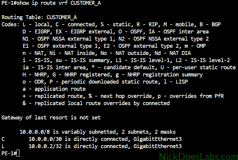
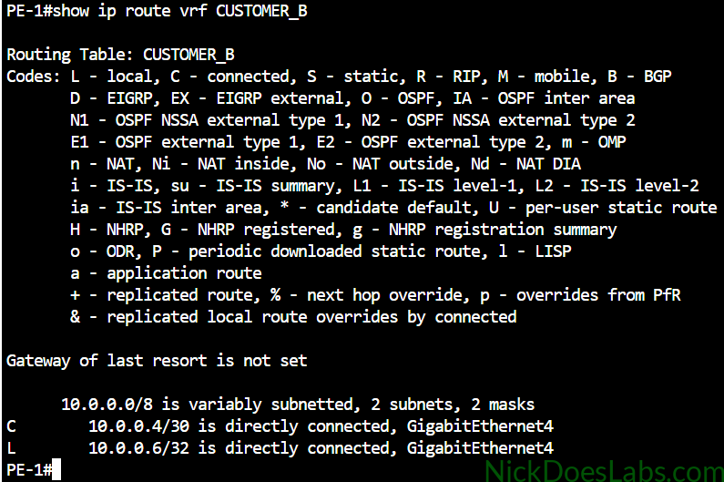
Next we will set up OSPF so that the CE routers can share their routes with the PE routers.
Step 3 – Configuring OSPF (CE-PE)
We need a way for the customers to share their routes with the service provider. While this can be done with any routing protocol, I’m going to use OSPF since it is popular in enterprise networking.
The routers will all be in OSPF area 0 and the only networks the customers are advertising are their loopbacks and their WAN interfaces. The router IDs have to be unique so that the PE routers don’t flag them as duplicate router IDs.
First we’ll configure the CE routers as follows:
!!!CE-1A!!!
router ospf 1
  router-id 10.10.10.10
  network 1.1.1.1 0.0.0.0 area 0
  network 10.0.0.0 0.0.0.3 area 0
  passive-interface Lo0
!!!CE-1B!!!
router ospf 1
router-id 11.11.11.11
network 1.1.1.1 0.0.0.0 area 0
network 10.0.0.4 0.0.0.3 area 0
passive-interface Lo0!!!CE-2A!!!
router ospf 1
router-id 12.12.12.12
network 2.2.2.2 0.0.0.0 area 0
network 10.0.0.8 0.0.0.3 area 0
passive-interface Lo0!!!CE-2B!!!
router ospf 1
router-id 13.13.13.13
network 2.2.2.2 0.0.0.0 area 0
network 10.0.0.12 0.0.0.3 area 0
passive-interface Lo0Next we will configure the provider edge routers. For these we will need to configure a separate process within each customer’s VRF to keep routes separate. Customer A will use OSPF process 1 and Customer B will use OSPF process 2. The PE routers can use the same Router ID to identify themselves for each process.
!!! PE-1 !!!
router ospf 1 vrf CUSTOMER_A
  router-id 1.1.1.1
  network 10.0.0.0 0.0.0.3 area 0
!
router ospf 2 vrf CUSTOMER_B
  router-id 1.1.1.1
  network 10.0.0.4 0.0.0.3 area 0
!!! PE-2 !!!
router ospf 1 vrf CUSTOMER_A
router-id 1.1.1.1
network 10.0.0.8 0.0.0.3 area 0
!
router ospf 2 vrf CUSTOMER_B
router-id 1.1.1.1
network 10.0.0.12 0.0.0.3 area 0At this point we can run show ip route vrf CUSTOMER_* and confirm that we have learned the customer’s loopback routes via OSPF in each VRF.
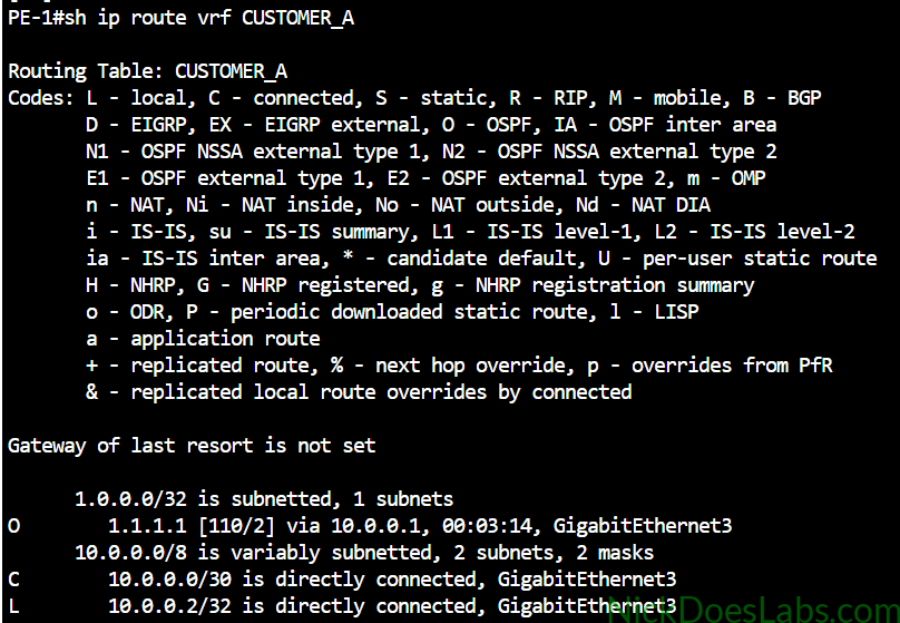
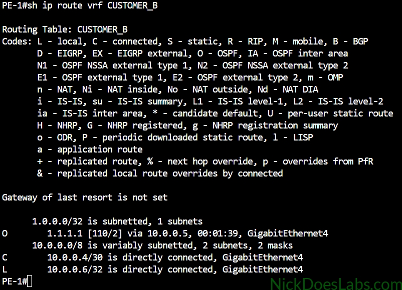
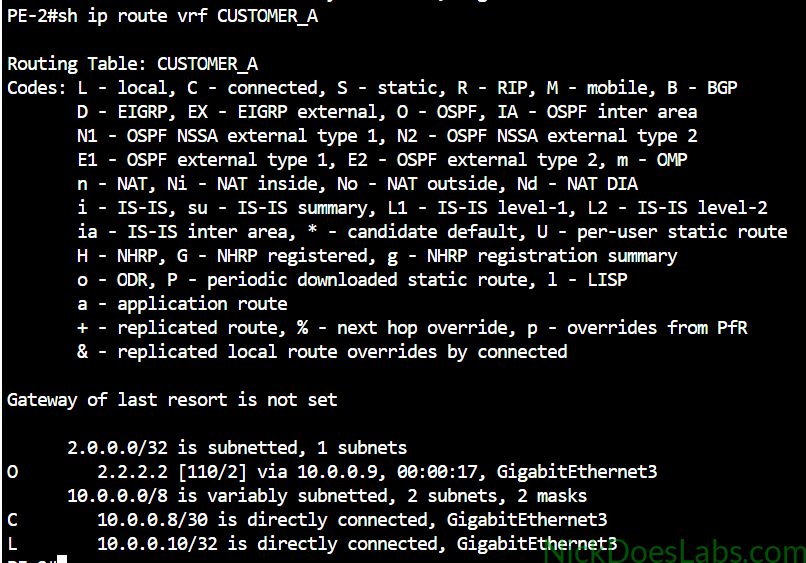
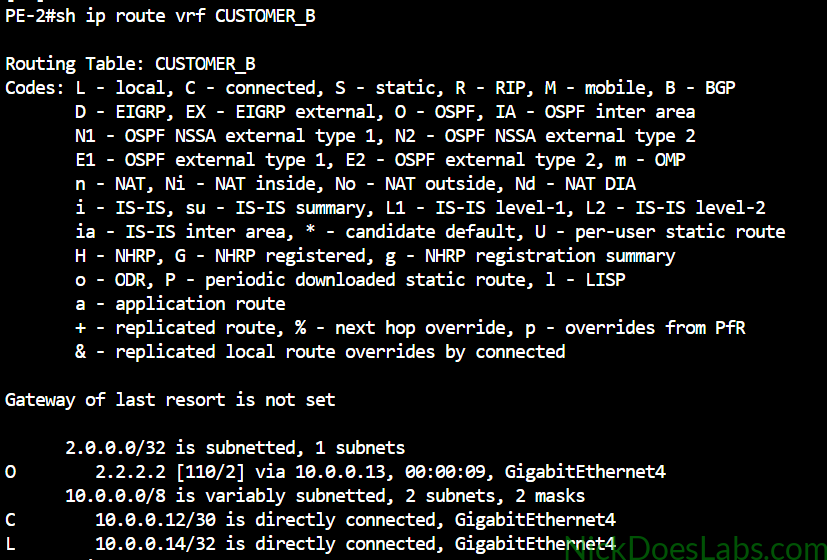
Now we are ready to share these routes between our PE routers. We will do this with BGP via VPNv4.
Step 4 – Configuring BGP (PE-PE)
At this point both PE routers know about the customer routes advertised by their directly connected OSPF neighbor (CE Router). Our goal is to get PE-1 and PE-2 to exchange those routes with each other. BGP is perfect for this for two reasons. First, BGP allows remote peering which means we can peer the two PE routers even though they could be in different cities, or even countries. As long as we have Layer 3 connectivity between them (we do through IS-IS), we can make them BGP neighbors. More importantly, BGP is the only routing protocol that supports VPNv4 (via MP-BGP) which will allow us to keep our customers’ routes separate from each other while they pass through the provider core.
We’ll start by configuring the peering between PE-1 and PE-2 with the following commands:
!!! PE-1 !!!
router bgp 500
  neighbor 3.3.3.3 remote-as 500
  neighbor 3.3.3.3 update-source Lo0
  address-family vpnv4 unicast
    neighbor 3.3.3.3 activate
!!! PE-2 !!!
router bgp 500
neighbor 1.1.1.1 remote-as 500
neighbor 1.1.1.1 update-source Lo0
address-family vpnv4 unicast
neighbor 1.1.1.1 activateOnce this is done we can verify the neighborship using the command show bgp vpnv4 unicast all neighbors:

Now we just need to pass the customer routes learned via OSPF into BGP and vice versa. But before we do that we need to add unique route distinguishers and route targets to our VRFs.
Step 4 – Configuring Route Distinguishers and Route Targets
Route distinguishers and route targets are components of VPNv4 which help keep customer routes and traffic segregated. The route distinguisher is a unique label which is added to customer routes to distinguish them from each other. This allows for what we call overlapping routes, customers using the same IPs. Because the IP is encapsulated in a route distinguisher, it doesn’t cause conflicts. Route targets tell the PE router which VRF to import the customer route to. I discuss these concepts in detail in this post: Provider Networking – Route Distinguishers vs Route Targets.
To configure the route distinguishers and route targets we will use the following commands on both PE routers. The Import route-target tells the router which routes to bring in to the VRF. The export route target tells the router what to label them as they leave the VRF. Also note that we are using address-family ipv4 since the customer routes getting put in the VRF will be ipv4. This is not to be confused with vpnv4 which we are using to transport them.
Note: It is recommended to use a unique route distinguisher for each PE. A good format is router-id:customer-id. This isn’t necessary in this lab because it is a basic example.
vrf definition CUSTOMER_A
 rd 500:1
 address-family ipv4 unicast
   route-target both 100:100
!
vrf definition  CUSTOMER_B
 rd 500:2
 address-family ipv4 unicast
route-target both 200:200| VRF Name | Route Distinguisher | Route Target |
|---|---|---|
| CUSTOMER_A | 500:1 | 100:100 |
| CUSTOMER_B | 500:2 | 200:200 |
Now we are ready to begin redistributing routes between BGP and OSPF.
Step 5 – Redistributing Routes
This final part is pretty straightforward. We have 2 routing protocols running. OSPF knows the path to each customer router but not the path through the provider network. BGP knows the path through the provider network but not to the customer routers. We are going to redistribute routes from each OSPF process into BGP, separating them by VRF. We are also going to do the reverse, and redistribute routes from BGP into OSPF.
Running these commands on both routers will accomplish this:
router bgp 500
  address-family ipv4 unicast vrf CUSTOMER_A
    redistribute ospf 1 vrf CUSTOMER_A
!
  address-family ipv4 unicast vrf CUSTOMER_B
      redistribute ospf 2 vrf CUSTOMER_B
!
router ospf 1 vrf CUSTOMER_A
  redistribute bgp 500
!
router ospf 2 vrf CUSTOMER_B
   redistribute bgp 500
At this point we can verify that our PE routers now see the routes from the other side of the VPN by running show ip route vrf [VRF NAME]:
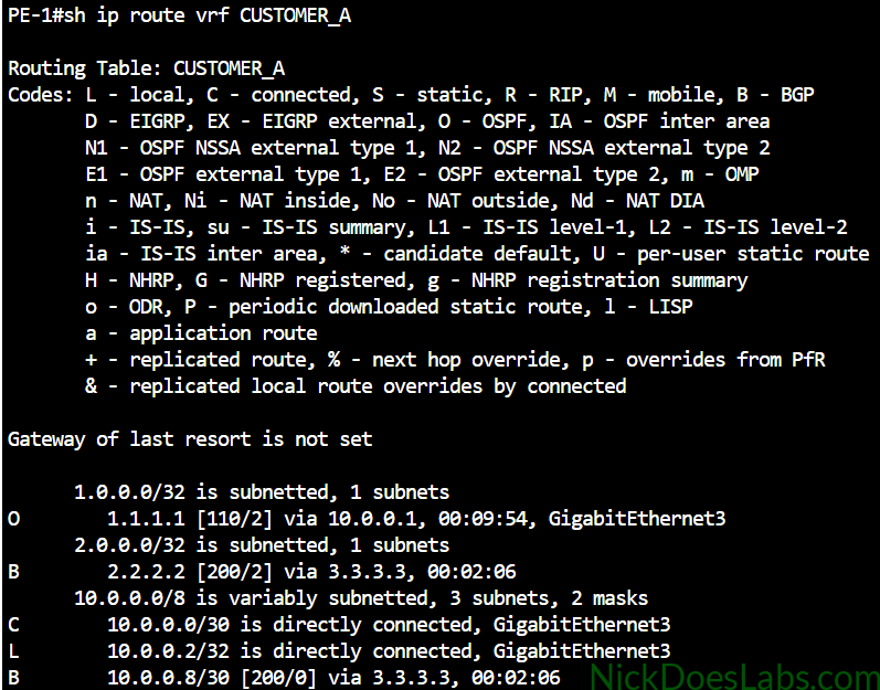
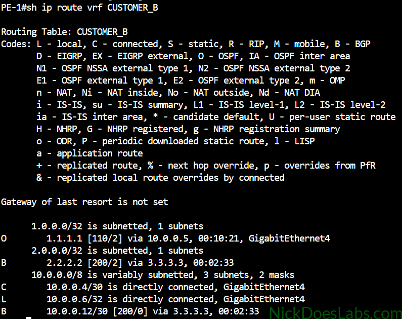
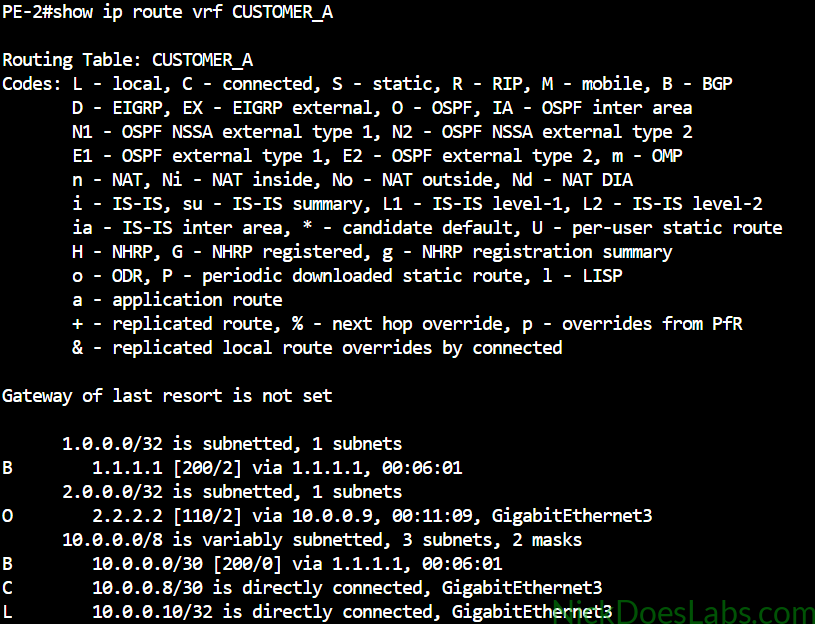
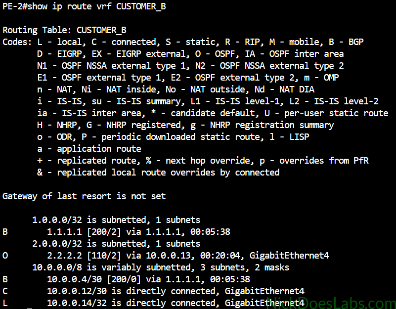
As we can see each PE router has learned the directly connected customer loopback through OSPF, and the remote customer loopback (and WAN subnet) through BGP. The routes have been segregated into separate routing tables that are private to each VRF.
Step 6 – Verifying the Layer 3 MPLS VPN
First we are going to go to each CE router and make sure we can ping the remote CE router through the VPN.

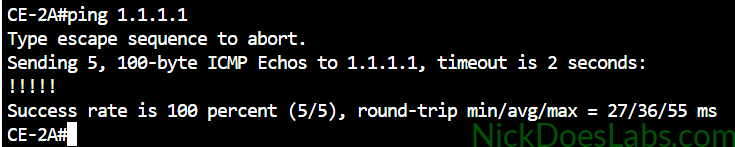

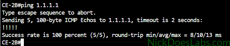
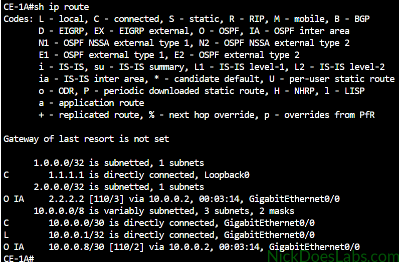
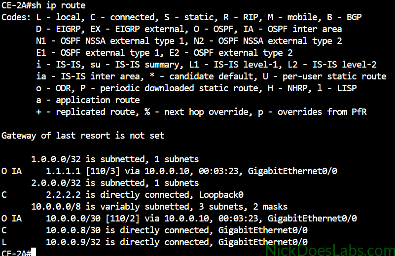
Pings are successful between the CE routers across the VPN. We can also check the routing tables on each CE router and we will see the remote routes marked as OSPF Inter Area since they were redistributed into OSPF.
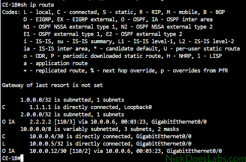
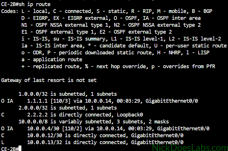
We can also take a peek behind the curtain and see the VPNv4 table on our PE routers with the command show ip bgp vpnv4 all:
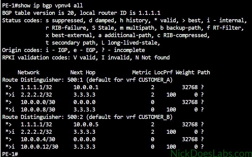
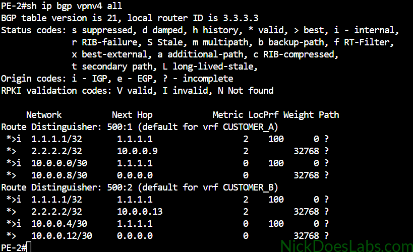
Here we can see that the customer routes are separated by their route distinguishers which is what really makes the magic happen.
I want to demonstrate one more thing since it is the key to understanding the Layer 3 MPLS VPN data plane. I’m going to run the command show ip bgp vpnv4 all labels:
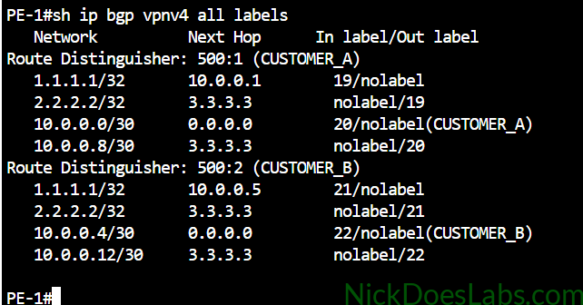
Here, in the far right column we can see the actual MPLS labels that are being shared automatically via MP-BGP. These labels will encapsulate the customer data, keeping it segregated as it crosses the MPLS core. For example when Customer A wants to send some data to 2.2.2.2, the router will prepend it with the MPLS label 19 before sending it out. It will then get a standard MPLS Transport label as well which will allow it to cross the core.
Conclusion
And that’s it! We have successfully configured Layer 3 MPLS VPN services for two customers and verified that they are working properly. We used VPNv4 (via MP-BGP), OSPF, VRFs, Route Distinguishers, and Route Targets to accomplish this, on top of our existing core that is running MPLS-LDP and IS-IS.
If you’d like to download the lab.yaml file for this lab as well as the router configurations, they are available for free here.