
Overview
In this lab we’ll build a provider-style MPLS Core with IOS XE in Cisco Modeling Labs. This lab will demonstrate step-by-step configuration of IS-IS, MPLS, and LDP on the Cisco CSR1000v. I previously published a lab demonstrating how to build a provider-style MPLS core using IOS XRd. Unfortunately, IOS XRd has certain limitations such as lack of support for Layer 2 Multipoint VPNs. Because of this I’ve decided to recreate my IOS XRd MPLS core lab using the CSR1000v IOS XE image. I also believe it is important to do labs with both IOS XE and IOS XR to become proficient in both operating systems.
Scenario
A service provider needs a core network that is able to move data efficiently between customers and the internet. It’s important that the core is scalable, and allows the provider to offer services such as Layer 3 VPNs and Layer 2 VPNs.
Method
We will construct a service provider core made of 2 provider routers and 2 provider edge routers. These four routers will use IS-IS as their interior gateway protocol in order to establish reachability between them. We won’t be using IP addresses on the point to point links inside this provider core, as this isn’t needed for IS-IS and reduces complexity. Each core router will use a loopback to identify itself and communicate with other routers. The provider edge (PE) routers will be responsible for providing service and connectivity to customers. The provider core (P) routers will be responsible for routing traffic as fast as possible using MPLS.
Equipment
- Provider Edge Routers (CSR1000v)
- PE-1
- PE-2
- Provider Core Routers (CSR1000v)
- P1
- P2
Step 1 – Adding and Staging the Nodes
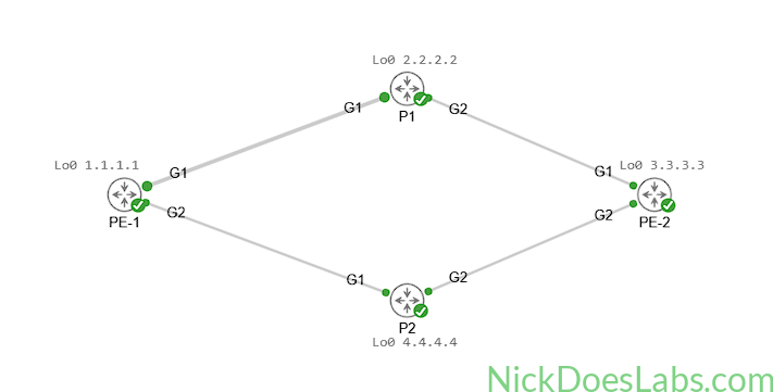
We’ll start by adding four CSR1000v nodes to our lab and interconnecting them as follows:
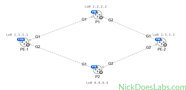
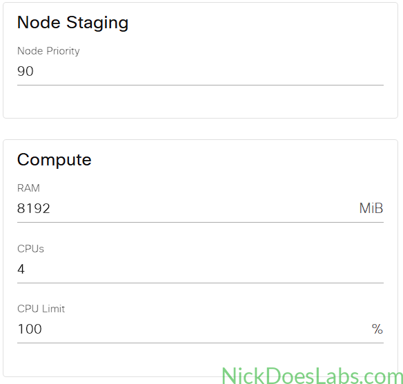
The CSR1000v image is very resource hungry, hungrier than IOS XRd. Make sure to enable node staging and stagger the priorities of each node. Also, make sure each node gets at least 8 Gb of RAM and 4 vCPUs.
Now we can power on the nodes and begin configuring them.
Step 2 – Configuring Loopback Addresses
On each router we will create an interface named Loopback 0 and assign it a unique IP. Now is a good time to set our hostnames and domain name too. Example:
hostname PE-1
ip domain name nickdoeslabs.com
int Lo0
  ip address 1.1.1.1 255.255.255.255
no shutdown| Router | Loopback |
|---|---|
| PE-1 | 1.1.1.1 |
| P1 | 2.2.2.2 |
| PE-2 | 3.3.3.3 |
| P2 | 4.4.4.4 |
With the loopbacks configured on all four routers we can now configure IS-IS.
Step 3 – Configuring IS-IS on IOS XE
First we’ll enable all of the interfaces connecting to other routers. We’ll also need to configure them with “isis network point-to-point” and “ip unnumbered Loopback0”. This lets IS-IS use the interfaces without them having IP Addresses. You can imagine that at scale, having a separate /30 subnet for each link between routers can become hard to manage. With this configuration the routers will identify themselves and forward traffic using their loopback interfaces only.
Here is the interface configuration demonstrated on PE-1:
interface G1
  description link to P1
  ip unnumbered Lo0
  isis network point-to-point
  no shutdown
interface G2
  description link to P2
  ip unnumbered Lo0
  isis network point-to-point
  no shutdown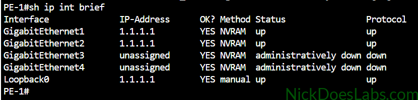
At this point our interfaces should all be Up/Up and the only IP addresses configured are the Loopbacks. Next we will create an IS-IS process for each router, naming it CORE. We will specify under the IS-IS configuration that Loopback 0 should be passive. The NET Address will have an area of 1 for all routers, and the host ID will align with the Loopback for each router. Ex. PE-1 will have a host ID of 1. Be sure to configure the correct interfaces and NET Addresses for each router.
Unlike IOS XR, we enable IS-IS on interfaces in interface config mode, not IS-IS config mode. Therefore, once the IS-IS process is created and the net address is assigned, we will go back to interface config mode and enable IS-IS on the interfaces. This is done with the command ip router isis [process name].
Here is an example of the configuration on PE-1 as well as a table of the net addresses:
router isis CORE
  net 49.0001.0000.0000.0001.00
  passive-interface Lo0
interface Lo0
  ip router isis CORE
interface G1
  ip router isis CORE
interface G2
ip router isis CORE | Router | Net Address |
|---|---|
| PE-1 | 49.0001.0000.0000.0001.00 |
| PE-2 | 49.0001.0000.0000.0003.00 |
| P1 | 49.0001.0000.0000.0002.00 |
| P2 | 49.0001.0000.0000.0004.00 |
Once this is done the routers should form neighborships which you can verify with show isis neighbors:
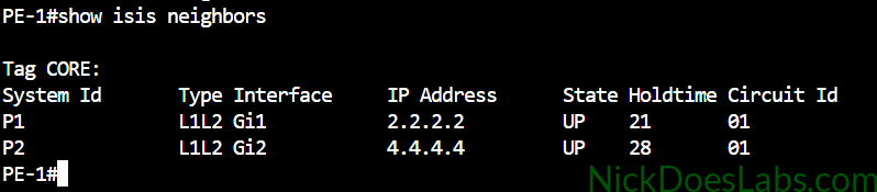
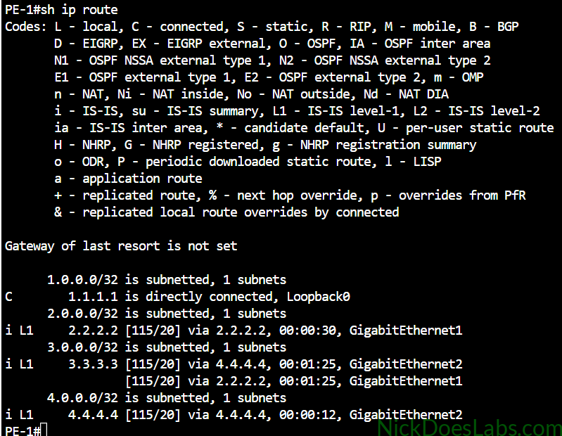
More importantly, they will exchange routing information for their Loopbacks. Every router now knows how to get to every other router. We can verify this in the routing table as demonstrated on PE-1:
With reachability established between all of our core routers we can move on to configuring MPLS.
Step 4 – Configuring MPLS on IOS XE
Configuring MPLS is pretty straightforward. We are going to run the following commands on each router. We are enabling MPLS OAM as well. MPLS OAM (Operations, Administration, and Maintenance) is a set of tools which allows us to monitor, diagnose, and troubleshoot MPLS.
Here is the configuration for all routers:
mpls oam
mpls ldp router-id Lo0
interface G1
  mpls ip
interface G2
mpls ip| Router | MPLS Router ID |
|---|---|
| PE-1 | 1.1.1.1 |
| PE-2 | 3.3.3.3 |
| P1 | 2.2.2.2 |
| P2 | 4.4.4.4 |
Once that is done, MPLS LDP will automatically generate and distribute labels for all the routers in the core. We can then verify this with show mpls forwarding-table to view the mpls forwarding database. We can also run show mpls ldp bindings to verify that each router has label bindings for every other router.
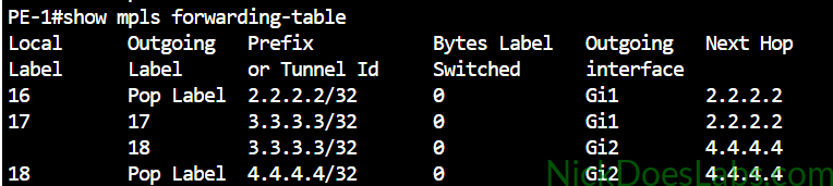
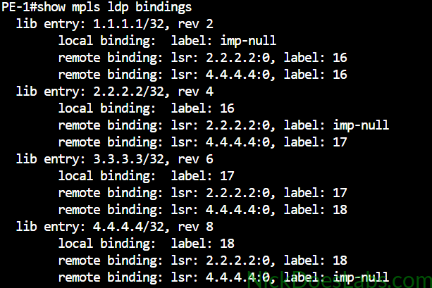
As you can see from the MPLS forwarding table, PE-1 has two paths to get to PE-2 (3.3.3.3). It can either send traffic to P1 at 2.2.2.2 or P2 at 4.4.4.4. When sending traffic to P1 or P2, PE-1 will pop (remove) the label since Penultimate-Hop Popping is enabled.
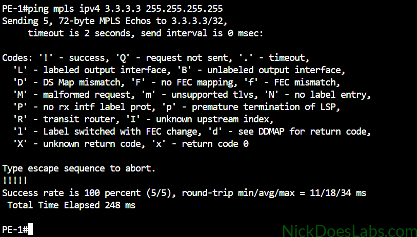
Since we’ve enabled MPLS OAM we can test mpls by running the command: ping mpls ipv4 3.3.3.3 255.255.255.255 on PE-1. An MPLS ping confirms that MPLS is working properly:
And that’s it! we now have a fully functional service-provider MPLS core in Cisco Modeling Labs. This will be the basis for many other labs where we will actually implement services such as L3VPN and L2VPN.
If you’d like to download the lab.yaml file for this lab as well as the router configurations, they are available for free here.