
Overview
Segment routing is a modern MPLS Traffic Engineering tool which is becoming more popular in service provider MPLS networks. In this lab we’ll implement segment routing on IOS XRd in Cisco Modeling Labs. Segment routing allows engineers to manipulate the path that traffic takes through an MPLS network. This is done by identifying routers with Segment Identifier (SID) labels. Those SID labels are pushed as a stack at the ingress router, allowing it to control the full path of the traffic based on policy.
Scenario
Our service provider has two customers to whom we are providing Layer 3 VPN services. By default, all traffic is being sent across our MPLS core based on the IS-IS best path. What this means is that, as we continue to add customers to our PE routers, traffic will continue to use the same path. The redundant path will sit underutilized while the active path gets congested. We want to avoid this by implementing MPLS traffic engineering with segment routing so that our resources are used efficiently.
Method
Segment routing distributes SIDs via the Interior Gateway Protocol (IGP). The IGP I am using for this lab is IS-IS. Therefore, my first step will be to configure IS-IS to support segment routing and advertise SIDs. Then, I’ll assign a Prefix SID to each router’s loopback interface. Next, I will verify that all core routers can see each other’s SIDs. Then, I’ll engineer two different paths through the network by creating two different segment lists. I’ll apply these segment lists to different policies and then apply those separate policies to our customer traffic. Because IS-IS handles SID distribution, we no longer need LDP. Therefore, I will disable LDP to conserve resources once segment routing is working.
Equipment
I’ll be starting with the topology I built in my Layer 3 MPLS VPN lab. You can download the configuration files and the lab.yaml here.
- Customer Edge Routers (IOSv)
- CE-1A
- CE-1B
- CE-2A
- CE-2B
- Provider Edge Routers (XRd)
- PE-1
- PE-2
- Provider Core Routers (XRd)
- P1
- P2
Prequel – How Traffic Flows Without Segment Routing
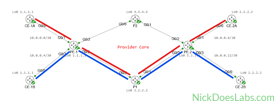
Without segment routing, traffic uses the IS-IS best path available in the routing table. This means that all traffic will follow the path IS-IS chooses through the network. Currently, IS-IS is using the PE-1 > P1 > PE-2 path.
We can verify this by running traceroutes from CE-1A to CE-2A and CE-1B to CE-2B.
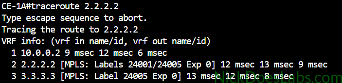
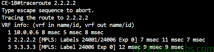
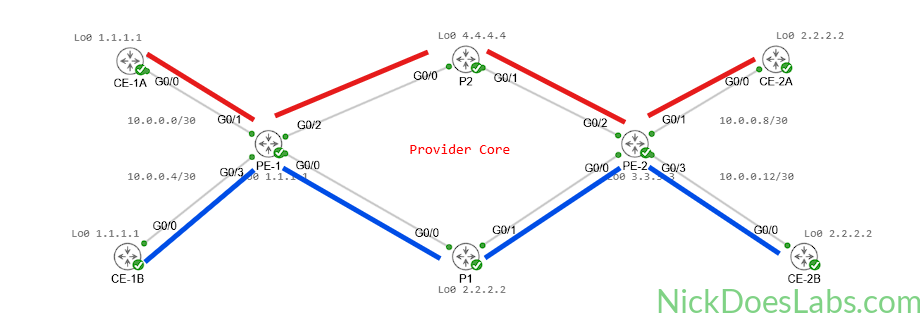
This means that the PE-1 > P2 > PE-2 path is underutilized, which is a waste of resources and adds congestion to the other path. Our goal is for traffic to be distributed fairly across both links so that we are maximizing the efficient utilization of our resources as you see below.
Step 1 – Configuring IS-IS for Segment Routing
First, we need to set the IS-IS metric style to wide on all of our core routers. IS-IS wide metric style allows it to carry traffic engineering information alongside normal routing information. This will allow IS-IS to advertise our segment routing SIDs. For a detailed explanation of IS-IS metric styles, see the Juniper Documentation. The command to set metric-style to wide is simply metric-style wide and we enter it under address-family configuration mode for IS-IS.
Next, we need to enable segment routing support in IS-IS. We also do this in address-family configuration mode. The command is simply segment-routing mpls.
We will run these commands on all of our PE and P routers, together the configuration is as follows:
router isis CORE
  address-family ipv4 unicast
    metric-style wide
    segment-routing mpls
Note that IS-IS can only share routing info with routers that have the same metric style. Therefore core routers will lose routes learned from neighbors as long as the metric style doesn’t match. So if you are doing this in a production network, you should use a migration strategy to maintain routing while transitioning the core to wide metrics.
Step 2 – Configuring the Segment Routing IDs (Prefix SIDs)
With IS-IS configured to support segment routing, our next step is to assign Prefix SIDs to all core routers. A Prefix SID on a router’s loopback interface is also known as a Node SID and it is how segment routing identifies our routers. Each router will get a unique Prefix SID attached to its loopback interface. IS-IS will advertise the Prefix SIDs between the core routers.
To configure the Prefix SID, we will enter IS-IS configuration mode for interface loopback 0 and address family ipv4 unicast. The command is prefix-sid absolute [SID]. On IOS XR the range of valid SID numbers is 16000-1048575. For our routers I will make each SID 16000 plus the IS-IS host ID. The SIDs will then match up with the host ID and loopback IP address as follows:
| Router Name | IS-IS Host ID | Lo0 IP Address | Prefix SID |
|---|---|---|---|
| PE-1 | 0000.0000.0001 | 1.1.1.1 | 16001 |
| P1 | 0000.0000.0002 | 2.2.2.2 | 16002 |
| PE-2 | 0000.0000.0003 | 3.3.3.3 | 16003 |
| P2 | 0000.0000.0004 | 4.4.4.4 | 16004 |
Here is an example of setting the Prefix SID on PE-1:
router isis CORE
  interface Lo0
    address-family ipv4 unicast
      prefix-sid absolute 16001
With all of our Prefix SIDs configured, we can now verify that IS-IS is advertising them properly.
Step 3 – Verifying SID Advertisement
On PE-1 I will run the command show mpls forwarding to view the MPLS forwarding table.
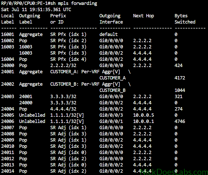
As you can see, our Prefix SIDs for all core routers are present in the MPLS forwarding table. However, because LDP is still running, the LDP labels (24000, 24003, and 24004) are being preferred over the SIDs. Note that 24001, 24002, 24005, and 24006 are VPNv4 labels, not LDP labels. We will fix this in our next step when we disable LDP.
I also want to demonstrate that IS-IS is advertising our SIDs. The command that I found to have the cleanest output for this is show isis segment-routing label.
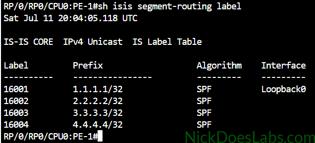
Here we can see that IS-IS has advertised all of our Prefix SIDs and matched them with the loopback prefixes.
Step 4 – Disabling Label Distribution Protocol
Label Distribution Protocol (LDP) is used to distribute MPLS labels. It has its own system of hello packets, adjacencies, and tables to maintain. Because IS-IS is distributing our Prefix SIDs as MPLS labels, we no longer need LDP and it is a waste of resources on our routers. Therefore, I’m going to disable LDP on all core routers.
To do this, I’m going to run the command no mpls ldp in global configuration mode on each PE and P router. I’ll then verify that LDP labels have disappeared from my forwarding table.
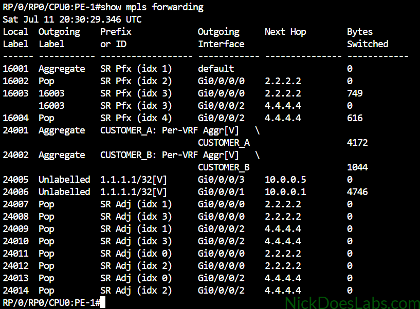
Again, note that 24001, 24002, 24005 and 24006 are not LDP labels; they are VPNv4 labels tied to our Layer 3 VPN services.
I can verify that our Prefix SIDs are being used as forwarding labels by looking up the labels for each Loopback address. I’ll do this with the command show mpls forwarding prefix [loopback].
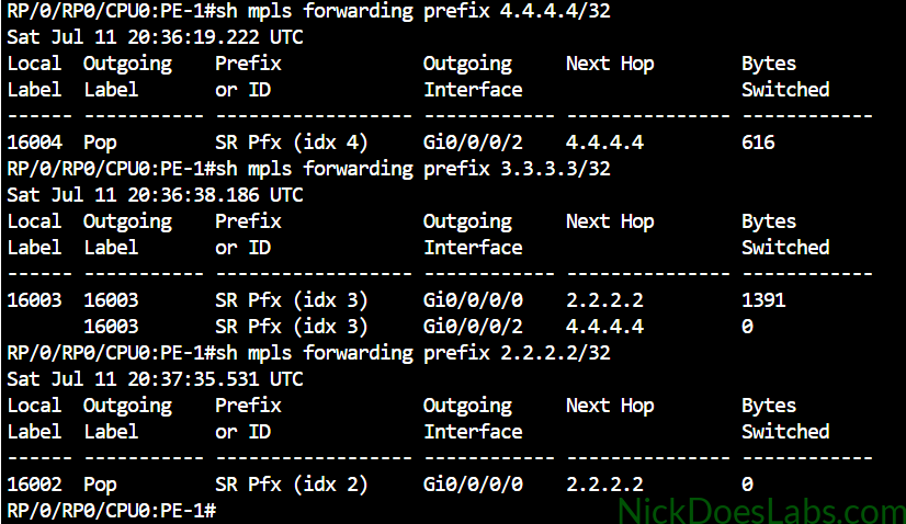
Penultimate Hop Popping (PHP) is enabled by default so PE-1 will pop the label for traffic going to P1 or P2. For traffic going to PE-2 it will use label 16003 which matches PE-2’s Prefix SID as expected.
It’s a good idea to verify that we can still ping across the core at this point.
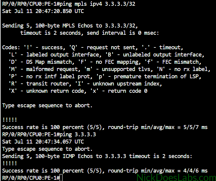
We’ve now thoroughly verified that our MPLS labels are distributed properly and are working after disabling LDP. We are ready to implement segment routing policies.
Step 5 – Creating the Segment Lists
A segment list is a list of Segment Identifiers (SIDs) that describes the path we want traffic to follow. For this demonstration, I want customer A’s traffic to flow through the top path PE-1 > P2 > PE-2 and customer B’s traffic to flow through the bottom path PE-1 > P1 > PE-2. Therefore I need to create two segment lists to describe these two paths. I will need to create the lists on PE-2 as well for the return traffic. This is because segment routing policies are unidirectional in nature, so a separate policy is needed in each direction.
My segment lists will look like this:
| Configured on Router | Path Name | Segment List (SIDs) |
|---|---|---|
| PE-1 | PE1-P1-PE2 | 16002 16003 |
| PE-1 | PE1-P2-PE2 | 16004 16003 |
| PE-2 | PE2-P1-PE1 | 16002 16001 |
| PE-2 | PE2-P2-PE1 | 16004 16001 |
To avoid confusion, I am naming the lists based on the hostnames along the path. As you can see the segment list contains the SIDs we want traffic to flow through after they leave the ingress router.
The configuration on each PE router looks like this:
!!!! PE-1 !!!!
segment-routing
  traffic-eng
    segment-list PE1-P1-PE2
      index 10 mpls label 16002
      index 20 mpls label 16003
    segment-list PE1-P2-PE2
      index 10 mpls label 16004
      index 20 mpls label 16003
!!!! PE-2 !!!!
segment-routing
traffic-eng
segment-list PE2-P1-PE1
index 10 mpls label 16002
index 20 mpls label 16001
segment-list PE2-P2-PE1
index 10 mpls label 16004
index 20 mpls label 16001The indexes describe the order of the path the traffic will follow. Traffic will flow from the lowest index to the highest index. In the data plane, the SID stack is constructed so that the SID for the first segment is the active top label. For example, the list PE1-P1-PE2 specifies a path through SID 16002 followed by SID 16003. This means that our core P routers don’t need to be aware of our segment lists or segment routing policies at all. The P routers simply process the active MPLS label and forward traffic accordingly.
With our segment lists created we can now create segment routing policies that will apply them.
Step 6 – Creating Segment Routing Policies
We are going to create two policies on each PE router, one for each segment list. This part can be a little confusing so I’m going to break it down piece by piece.
First, we will need to assign a color and endpoint to each policy. The color/endpoint combination must be unique for each endpoint, since it is used by the router to identify the policy. In segment routing a color is not an actual color like red green or blue. Instead, it’s a number between 1 and 4294967295. For simplicity I will use 100 and 200 to identify my policies.
policy USE_P1
  color 100 end-point ipv4 3.3.3.3
Next, we need to assign a path to our policy. We do this under candidate-paths configuration mode for the policy. The candidate path will reference one of the segment lists that we created earlier. Now, it’s important to understand that a policy can have multiple candidate paths, but only one candidate path is active at a time. The active path is chosen based on a preference value and if the preferred candidate path becomes unavailable, another eligible candidate path can be selected. Therefore we will enter a preference level first before we assign our segment list. Since we only have one candidate path for this lab, I’ll just use a preference of 100.
candidate-paths
  preference 100
Finally, we will assign the segment list to the policy, under preference 100. We will assign it as explicit, since it is a preconfigured path. The other option is dynamic which I’ll cover in a future lab.
explicit segment-list PE1-P1-PE2The complete configuration for both PE routers looks like this:
!!!! PE-1 !!!!!
segment-routing
  traffic-eng
    policy USE_P1
    color 100 end-point ipv4 3.3.3.3
    candidate-paths
      preference 100
        explicit segment-list PE1-P1-PE2
  policy USE_P2
    color 200 end-point ipv4 3.3.3.3
    candidate-paths
      preference 100
        explicit segment-list PE1-P2-PE2
!!!! PE-2 !!!!
segment-routing
traffic-eng
policy USE_P1
color 100 end-point ipv4 1.1.1.1
candidate-paths
preference 100
explicit segment-list PE2-P1-PE1
policy USE_P2
color 200 end-point ipv4 1.1.1.1
candidate-paths
preference 100
explicit segment-list PE2-P2-PE1Step 7 – Verifying the Segment Routing Policies
With these configurations set, we can now verify our SR “Tunnels” with the command show segment-routing traffic-eng policy tabular.
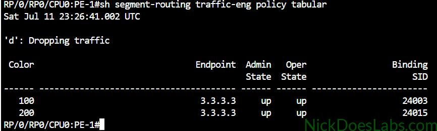
To view more details we can run the command show segment-routing traffic-eng policy. This output is pretty large so I’ll just show the first part.
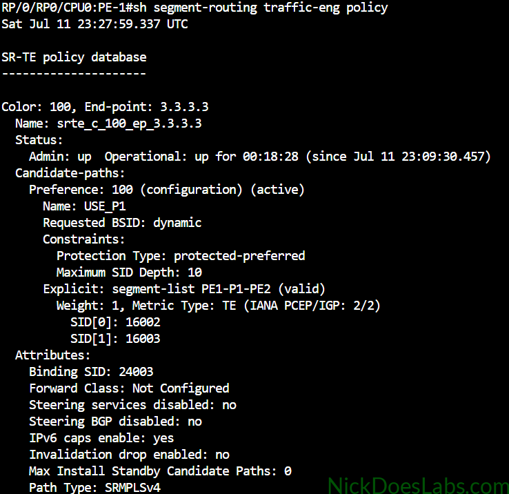
If you look at the “Name:” attribute you will see what I meant about the color and endpoint combination having to be unique. The router names the policy based on the color and endpoint. You can also see our candidate path, with our explicit segment list alongside some other details.
Now that our policies are configured and operational, we need to steer traffic into them.
Step 8 – Steering Traffic with Segment Routing
There are a few different ways to steer traffic into a segment routing policy. For this lab I’m going to use the BGP Color Extended Community because it is a common method of steering BGP routes into SR policies. We already have BGP set up to exchange VPNv4 routes between PE routers so we will be adding to that configuration.
We need to create two small route policies that will set the color of our customers’ routes. But we need to create an extcommunity-set first. The extcommunity-set will simply map our numerical color value to a more human-readable name. We will then identify the color by the extcommunity-set name in our route policy. The configuration for this is as follows on both PE routers.
extcommunity-set opaque CUSTOMER_A_COLOR
  200
end
extcommunity-set opaque CUSTOMER_B_COLOR
  100
end
!
route-policy CUSTOMER_A
  set extcommunity color CUSTOMER_A_COLOR additive
  pass
  end
route-policy CUSTOMER_B
  set extcommunity color CUSTOMER_B_COLOR additive
  pass
  end
Note: “additive” means the color extended community will be added without replacing the route’s existing extended communities, such as its route targets.
Next, we are going to apply the coloring policy at the point where we redistribute from our customers’ OSPF processes into BGP. By applying the extended attribute here, BGP will now advertise the customer’s IPv4 routes to the remote PE router alongside the color. This means, essentially, that PE-1 will tell PE-2 to use color 200 for CUSTOMER_A and PE-2 will tell PE-1 to use color 200 for CUSTOMER_A.
The commands to apply these policies are as follows on both PE routers:
router bgp 500
  vrf CUSTOMER_A
    address-family ipv4 unicast
      redistribute ospf CUSTOMER_A route-policy CUSTOMER_A
  vrf CUSTOMER_B
    address-family ipv4 unicast
      redistribute ospf CUSTOMER_B route-policy CUSTOMER_B
commit
With the coloring policies applied we now need to verify them. We can confirm this with the long command show bgp vrf [vrf name] ipv4 unicast [prefix] detail.
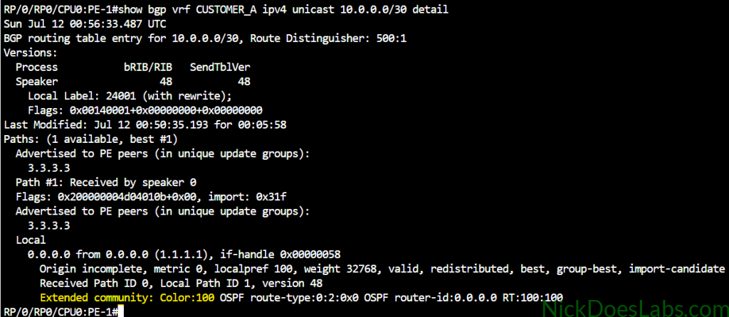
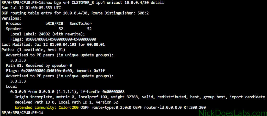
We can see that the appropriate color has been applied as an extended community for each customer’s BGP routes.
Finally, we can verify that traffic is flowing correctly based on our segment routing policies.
Step 9 – Verifying Segment Routing Traffic Engineering
We can verify segment routing both from our customer routers and from our PE routers. I’ll start by running traceroutes between the CE routers for both customers.
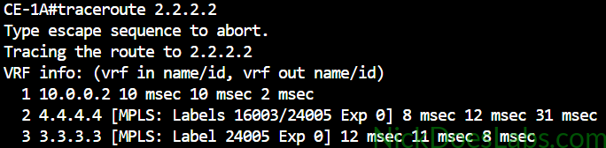
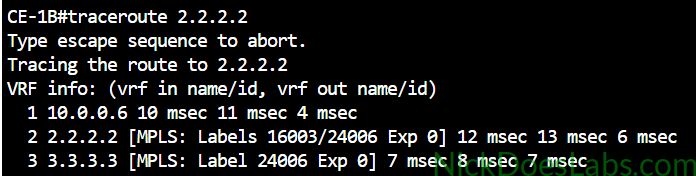
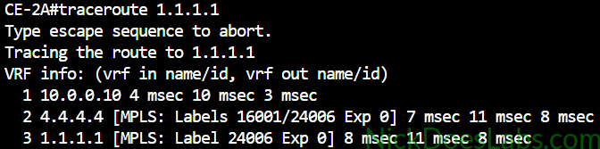
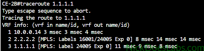
As you can see Customer A’s traffic is taking the top path via P2 and Customer B’s traffic is taking the bottom path via P1. This indicates that traffic is following our segment routing policies.
Next, I’ll check the CEF table on the PE routers to confirm how L3VPN traffic is being handled in the data plane. I’ll use the command show cef vrf [Customer] [Remote Prefix] brief.
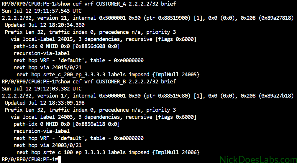
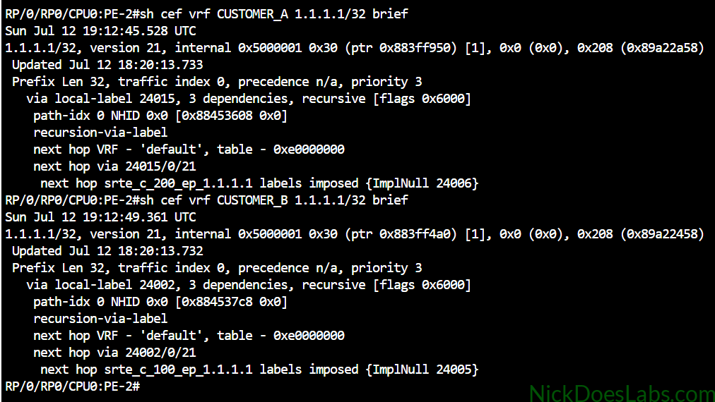
What we’re interested in here is the next hop data at the bottom of the outputs. You can see that Customer A traffic is using our segment routing traffic engineering (srte) color 200 policy and Customer B traffic is using color 100.
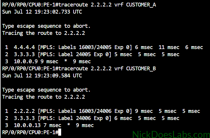
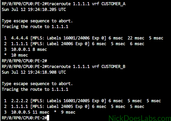
Finally, I can run VRF-specific traceroutes on each PE router to verify the traffic paths.
Conclusion
At the beginning of the lab all of our customer traffic was following the same path via P1 across our MPLS core. This left the path via P2 unutilized and resulted in unnecessary congestion of the P1 path. This is the default behavior of routers without traffic engineering. By default they follow the best path determined by the IGP. We successfully implemented Segment Routing, and used IS-IS to distribute our Prefix SIDs throughout the core. We then disabled LDP since it was now redundant and wasting resources.
Next, we created segment lists describing two different paths through the network and applied those lists to distinct segment routing policies identified by different colors. Finally, we used the BGP extended color community to assign our customer routes to separate colors. This forced each customers’ traffic along a different path through the network, improving the utilization of our available core links. This is a basic implementation of Segment Routing Traffic Engineering (SR-TE).
You can download the completed lab.yaml file as well as configuration files for each router here.