
Overview
I’ve done labs on Layer 2 and Layer 3 VPNs, but I haven’t yet demonstrated how providers connect customers to the Internet. I also needed a working lab to practice BGP peering and path manipulation. In this lab we will simulate an Internet Edge in Cisco Modeling Labs using BGP. The Internet Edge is where ISPs peer with other ISPs at Internet Exchange Points or Carrier Hotels. Peering is done using eBGP between the two different providers. The Internet Edge (IE) routers then use iBGP to share their routes with route reflectors in the provider network. Those route reflectors then share the routes with PE routers or BRAS/BNG routers.
Scenario
A regional ISP has two Internet Edge routers at two different exchange points. They need to configure eBGP and iBGP to receive the Internet routing table and distribute it to their PE routers. Our ISP has two customers who have purchased Internet access.
Method
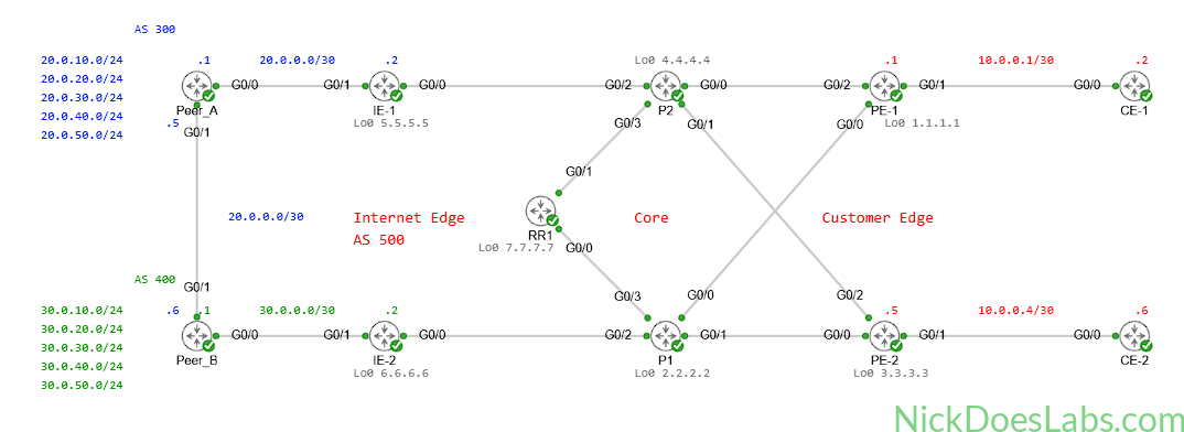
IE_1 and IE_2 will be our Internet Edge routers. We will need to configure eBGP peering between them and their peers. Peer_A and Peer_B will both have a simulated Internet routing table with the same 10 routes. IE_1 and IE_2 will peer via iBGP to RR1. They will use the next-hop self configuration so that traffic to those learned networks is forwarded to them. Our PE routers will also peer via iBGP to the route reflector so that they learn the routes that the IE routers have learned. We will give our customers static IP addresses and a default route pointing towards their respective PE router.
Equipment
I’ll be using a topology I built specifically to simulate Internet service delivery. You can download the lab.yaml as well as the individual configuration files here. In this topology I have already configured IP reachability between all routers as well as MPLS within the provider core. If you want to see how to configure IS-IS and MPLS, see Building a Service Provider MPLS Core in Cisco Modeling Labs.
- Customer Edge Routers (IOSv)
- CE-1
- CE-2
- Provider Edge Routers (XRd)
- PE-1
- PE-2
- Provider Core Routers (XRd)
- P1
- P2
- Internet Edge Routers (XRd)
- IE-1
- IE-2
- Peer ISP Routers (XRd)
- Peer_A
- Peer_B
Prequel – Configuring the Mock Internet Routes
Both peer routers have been configured with five loopbacks each of which represents a different subnet. Our goal is to get them to share routes to these networks with each other as well as our IE routers via eBGP. The loopback IP Addresses and the networks they represent are summarized in this table:
| Router | Loopback | IP Address | Network |
|---|---|---|---|
| Peer_A | Lo0 | 20.0.10.1 | 20.0.10.0 /24 |
| Peer_A | Lo1 | 20.0.20.1 | 20.0.20.0 /24 |
| Peer_A | Lo2 | 20.0.30.1 | 20.0.30.0 /24 |
| Peer_A | Lo3 | 20.0.40.1 | 20.0.40.0 /24 |
| Peer_A | Lo4 | 20.0.50.1 | 20.0.50.0 /24 |
| Peer_B | Lo0 | 30.0.10.1 | 30.0.10.0 /24 |
| Peer_B | Lo1 | 30.0.20.1 | 30.0.20.0 /24 |
| Peer_B | Lo2 | 30.0.30.1 | 30.0.30.0 /24 |
| Peer_B | Lo3 | 30.0.40.1 | 30.0.40.0 /24 |
| Peer_B | Lo4 | 30.0.50.1 | 30.0.50.0 /24 |
Step 1 – Configuring eBGP on the Peer Routers
We will configure eBGP between the two peer routers and between the peer and IE routers. Peer_A has the Autonomous System (AS) number 300 and Peer_B is 400. Our ISP’s AS number will be 500. I’ve summarized the interface IP addresses for the Peer and IE routers in the following table:
| Router | Interface | IP Address /Mask | Description |
|---|---|---|---|
| Peer_A | Gi0/0/0/0 | 20.0.0.1 /30 | Link to IE-1 |
| Peer_A | Gi0/0/0/1 | 20.0.0.5 /30 | Link to Peer_B |
| Peer_B | Gi0/0/0/0 | 30.0.0.1 /30 | Link to IE-2 |
| Peer_B | Gi0/0/0/1 | 20.0.0.6 /30 | Link to Peer_A |
| IE-1 | Gi0/0/0/0 | IP Unnumbered (Lo0) | Link to Core |
| IE-1 | Gi0/0/0/1 | 20.0.0.2 /30 | Link to Peer_A |
| IE-2 | Gi0/0/0/0 | IP Unnumbered (Lo0) | Link to Core |
| IE-2 | Gi0/0/0/1 | 30.0.0.2 /30 | Link to Peer_B |
For each peer router we will enter bgp configuration mode with the command router bgp [AS#]. Here we specify our neighbors with the command neighbor [neighbor IP]. Then we need to specify the neighbor’s AS number with remote-as [AS#] and its address family with address-family ipv4 unicast. We will then exit back to BGP configuration mode on the local router. Here we will enter the address family configuration mode for the local router with address-family ipv4 unicast. This is where we will specify the networks we want to advertise.
The eBGP config for each peer router looks like this:
!!! on Peer_A !!!
router bgp 300
  neighbor 20.0.0.2
    remote-as 500
    address-family ipv4 unicast
  neighbor 20.0.0.6
    remote-as 400
    address-family ipv4 unicast
      exit
    exit
  address-family ipv4 unicast
    network 20.0.10.0/24
    network 20.0.20.0/24
    network 20.0.30.0/24
    network 20.0.40.0/24
    network 20.0.50.0/24
!!! on Peer_B !!!
router bgp 400
neighbor 30.0.0.2
remote-as 500
address-family ipv4 unicast
neighbor 20.0.0.5
remote-as 300
address-family ipv4 unicast
exit
exit
address-family ipv4 unicast
network 30.0.10.0/24
network 30.0.20.0/24
network 30.0.30.0/24
network 30.0.40.0/24
network 30.0.50.0/24At this point our neighborship between the Peer routers will come up and we can verify that with show bgp neighbors brief:
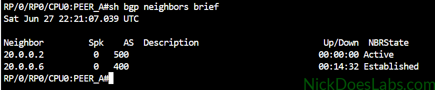
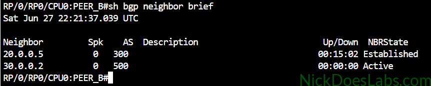
However, NO routes will be shared. At this point I was confused but I asked ChatGPT1 about it and learned that IOS XR will not advertise or accept any routes over eBGP unless you explicitly attach a route policy. So if you are wondering why eBGP isn’t working on IOS XR, this may be why. We can actually verify this by running the command show bgp neighbor 20.0.0.6 on Peer_A.
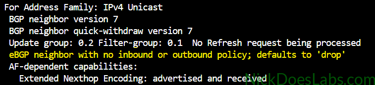
This lab isn’t focused on BGP policy, I will do future labs on that. Therefore we are going to fix this by creating a route policy named PASS_ALL that will pass (allow) all routes. We will then apply this policy inbound and outbound on each neighbor. The configurations for this are:
!!! on Peer_A !!!
route-policy PASS_ALL
  pass
  exit
router bgp 300
  neighbor 20.0.0.2
    address-family ipv4 unicast
      route-policy PASS_ALL in
      route-policy PASS_ALL out
  neighbor 20.0.0.6
    address-family ipv4 unicast
      route-policy PASS_ALL in
      route-policy PASS_ALL out
!!! on Peer_B !!!
route-policy PASS_ALL
pass
exit
router bgp 400
neighbor 30.0.0.2
address-family ipv4 unicast
route-policy PASS_ALL in
route-policy PASS_ALL out
neighbor 20.0.0.5
address-family ipv4 unicast
route-policy PASS_ALL in
route-policy PASS_ALL outWith this policy created and applied we can now verify that Peer_A and Peer_B are learning each other’s routes. To only show the BGP routes in the routing table I’ll use the command show ip route bgp.
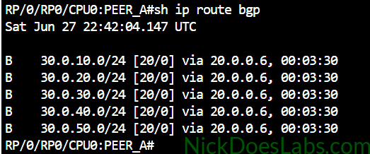

At this point we can move on to configuring the IE routers.
Step 2 – Configuring eBGP on the Internet Edge Routers
We will configure eBGP first before we worry about iBGP. IE-1 will peer with AS 300 Peer_A at 20.0.0.1 and IE-2 will peer with AS 400 Peer_B at 30.0.0.1. The configuration steps for eBGP are the same as we saw in step 1. This time we will make sure to create the route-policy first and apply it while we are in neighbor configuration mode. We won’t advertise any networks manually because the routes will be learned from the route reflector via iBGP. Routes learned via iBGP are advertised in eBGP automatically with no redistribution command needed.
The eBGP configurations for IE-1 and IE-2 look like this:
!!! IE-1 !!!
route-policy PASS_ALL
  pass
  exit
router bgp 500
  address-family ipv4 unicast
  neighbor 20.0.0.1
    remote-as 300
    address-family ipv4 unicast
      route-policy PASS_ALL in
      route-policy PASS_ALL out
      exit
    exit
!!! IE-2 !!!
route-policy PASS_ALL
pass
exit
router bgp 500
address-family ipv4 unicast
neighbor 30.0.0.1
remote-as 400
address-family ipv4 unicast
route-policy PASS_ALL in
route-policy PASS_ALL out
exit
exitWe will verify that our eBGP neighborships came up using the command show bgp neighbor brief. We will also verify that the internet routes have been learned using the command show ip route bgp.
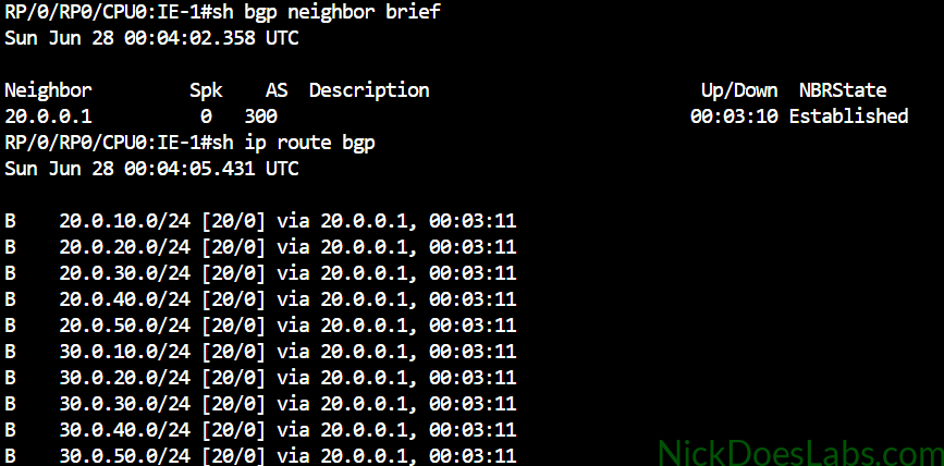
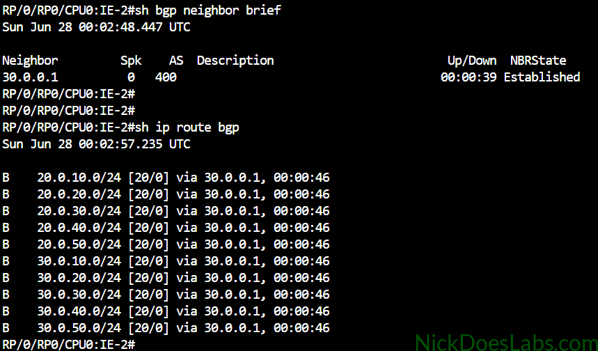
As you can see, each router has learned the full internet table since the peer routers both know each other’s routes. This will form the basis for future labs where we will use BGP policy to choose which peer we send traffic to.
We are now ready to configure iBGP.
Step 3 – Configuring iBGP on the Internet Edge Routers
This step is pretty brief. We simply need to configure each IE router to peer with our route reflector. We’ll do this using a neighbor command like we did for eBGP. For iBGP our remote-as will be 500, matching the local router’s AS. We don’t need to apply our PASS_ALL policy here since the default drop behavior only applies to eBGP. We will also specify the address family as ipv4 unicast and configure next-hop-self.
Next-hop-self is important because by default iBGP does not change the next-hop address of routes learned via eBGP. This means that without the next-hop-self command, routes would be shared to RR1 with a next hop of 20.0.0.1 or 30.0.0.1. These are external IP addresses which aren’t a part of our IS-IS routing domain (they shouldn’t be). Therefore the only routers in our network with routes to those IPs are the IE routers that are directly connected to them. Next-hop-self exists for this purpose and tells the IE routers to change the next hop to their own IP when sharing routes to the route reflector. We will also set update-source to Loopback 0 which tells the routers to use Lo0 to form the neighborship with RR1.
The configuration on our IE routers looks like this:
router bgp 500
  neighbor 7.7.7.7
    update-source Lo0
    remote-as 500
    address-family ipv4 unicast
      next-hop-self
Next, let’s configure RR1 and confirm we are learning the routes from the IE routers.
Step 4 – Configuring the Route Reflector
On the route reflector I will create two neighbor-groups, one for PE routers and one for IE routers. Right now they will be configured the same but in the future we may want to apply different policies for the different types of edge routers. Underneath the neighbor group we will configure the settings that apply to those neighbors, including the remote-as (500) and the address family (ipv4). Under the address-family configuration we will add route-reflector-client since these neighbors are clients of this route reflector. We will then use the command neighbor [IP Address] use neighbor-group [group].
The configuration for RR1 looks like this:
router bgp 500
  neighbor-group IE
    remote-as 500
    address-family ipv4 unicast
      route-reflector-client
  neighbor-group PE
    remote-as 500
    address-family ipv4 unicast
      route-reflector-client
    commit
    neighbor 5.5.5.5 use neighbor-group IE
    neighbor 6.6.6.6 use neighbor-group IE
    neighbor 1.1.1.1 use neighbor-group PE
    neighbor 3.3.3.3 use neighbor-group PE
commit
With this configuration complete we can verify that our iBGP neighborships are established with our IE routers and RR1 sees their routes.
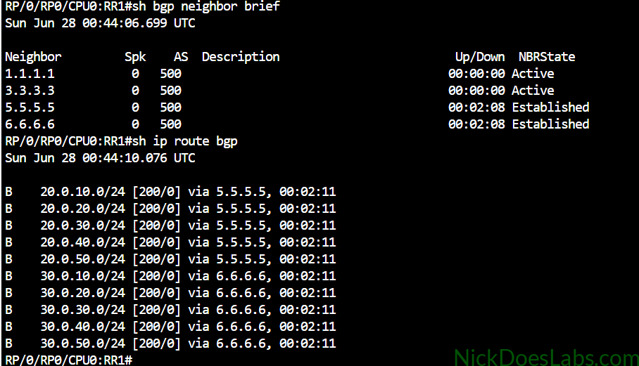
Notice that the route reflector has selected the best path through the Internet Edge router closest to the route origin. This is an example of BGP best-path selection. There are fewer hops to 20.0.0.0 /16 via 5.5.5.5 and to 30.0.0.0 /16 via 6.6.6.6. We will modify this using BGP policy in future labs. Also note that the next hop has been updated to the Lo0 IP address of the IE router.
Finally we need to configure our PE routers.
Step 5 – Configuring iBGP on the Provider Edge Routers
On the Provider Edge routers we are going to peer via iBGP with the route reflector. We will also originate the networks that we are assigning to our customer routers using the network command. This will allow those routes to be shared with the route reflector, and by extension they will be shared out to the IE routers and the internet. These networks are 10.0.0.0/30 for PE-1 and 10.0.0.4/30 for PE-2.
The configurations for the PE routers are as follows:
!!! On PE-1 !!!
router bgp 500
  neighbor 7.7.7.7
    remote-as 500
    update-source Lo0
    address-family ipv4 unicast
    exit
  exit
  address-family ipv4 unicast
    network 10.0.0.0/30
!!! On PE-2 !!!
router bgp 500
neighbor 7.7.7.7
remote-as 500
update-source Lo0
address-family ipv4 unicast
exit
exit
address-family ipv4 unicast
network 10.0.0.4/30Once the PE routers are configured we can verify our neighborships and confirm that we see a full internet table on each PE router.
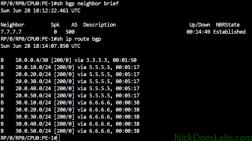
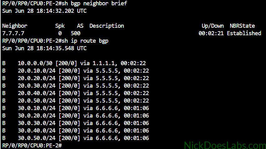
Note: In the real world providers may not give Multi-Service PE routers a full internet routing table. The full internet routing table has around 1 million prefixes and consumes significant resources. If a PE router is also performing VPN services or BRAS functions, it may just have a default route to another core router known as an Internet Gateway. The Internet Gateway router will then process all internet traffic based on the full internet BGP table.
Lets also confirm that our IE routers have received our customer routes and have shared them with the peer routers.
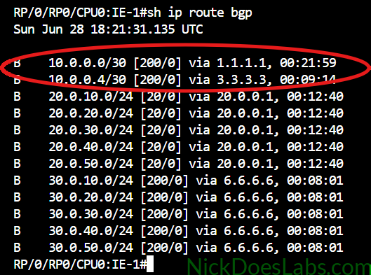
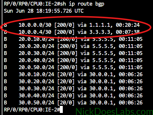
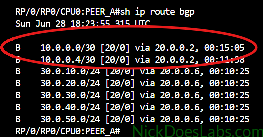
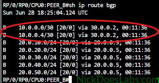
Excellent, our IE routers have learned the routes to our customers from the route reflector. They have then shared those routes with their respective internet peers. The peer routers have installed our customer routes in their routing tables.
Finally, we will configure our CE routers.
Step 6 – Configuring the Customer Edge Routers
Each customer will be given the IP address of its connected PE router so that they can install a default static route to our network. Once this is done the CE routers will be able to send and receive traffic from the Internet networks originated by Peer_A and Peer_B.
The configuration for the CE routers looks like this:
!!! On CE-1 !!!
ip route 0.0.0.0 0.0.0.0 10.0.0.1
!!! On CE-2 !!!
ip route 0.0.0.0 0.0.0.0 10.0.0.5Note: Some dual-homed / multi-homed enterprises may want a full or partial internet routing table so that they can apply BGP policy themselves. This is outside the scope of this lab but I will do a future lab on it.
With our default routes applied, we can test connectivity to the internet from our CE routers.
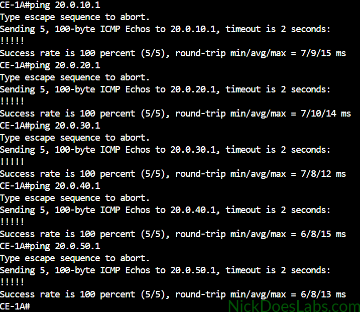
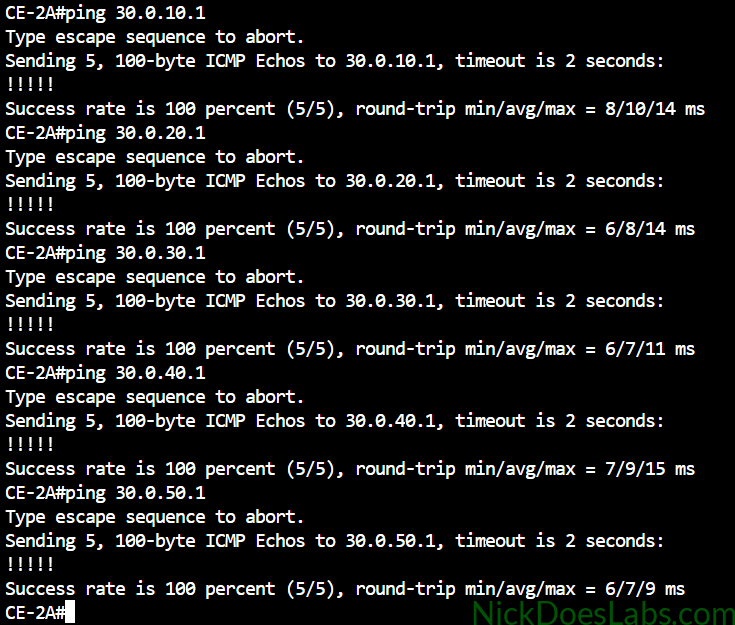
Both CE routers can ping to the 20.0.0.0/16 and 30.0.0.0/16 prefixes originated on the internet peers.
Conclusion
We have successfully built connectivity from our customer routers to the internet using eBGP and iBGP. Our Internet Edge routers both learn the full internet routing table from Peer routers at Internet Exchange Points. This routing table is then shared via iBGP with our route reflector. Our route reflector reflects those routes to our PE routers. Our PE routers share our customer-facing networks to the route reflector, which reflects those routes to the IE routers and by extension the internet. Finally our Customer Edge routers receive a default route to the PE for their internet traffic.
This was a time-consuming lab but now we have a base topology which we can use for future labs on BGP policy such as local-preference, weight, route maps, and as-path prepending. Thanks for following along and stay tuned for these future labs.
You can download the completed lab bundle, with configuration files and the lab.yaml here: ISP_BGP_Lab_configs.
- I do use AI for troubleshooting, fact-checking, proofreading and for generating certain infographics since I am no artist. However none of my lab content is generated by AI, and in information articles I only use AI for proofreading and accuracy checking. ↩︎